Specifying Element Activation and Eigenstrain Using the Pattern-Based Method
The following steps are required to use the pattern-based eigenstrain method:
- Create a table collection with a name that begins with "ABQ_EIG". The table collection must contain a parameter table of type "ABQ_AM_EigenStrain_Method" as well as the other parameter tables listed below.
- In the parameter table of type "ABQ_AM_EigenStrain_Method", set the activation type to "PatternBased".
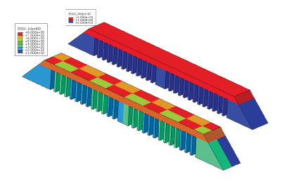
- Define parameters of rectangular patches that make up a rectangular unit cell (see Scan Pattern–Mesh Intersection), which is repeated to cover the cutting plane or a layer, in a parameter table of type "ABQ_AM_EigenStrain_PatternBased_Define". You can define the following parameters: a local angle, ; the extents of a patch and ; and a label of the parameter table defining an eigenstrain to apply to this patch.
- Define the six eigenstrain components in a parameter table of type "ABQ_AM_EigenStrain_Define".
- Define the parameters of the bounding box, inside which a particular scan-pattern strategy is active, in a parameter table of type "ABQ_AM_EigenStrain_PatternBased_ScanStrategy_Define".
- Define the build parameters (such as slice or layer thickness and build coordinate system) in a parameter table of type "ABQ_AM_EigenStrain_PatternBased_Activation".
- Optionally, include a parameter table of type "ABQ_AM_EigenStrain_Activation_Advanced" to specify advanced options.
- Refer to the table collection in the progressive element activation.
A dedicated collection of parameter table, property table, and event series types is available to include all of the definitions required by special-purpose techniques for additive manufacturing. You can use the abaqus fetch utility to obtain the file containing all of the type definitions of parameter tables, property tables, and event series required by the special-purpose techniques for additive manufacturing as follows:
abaqus fetch job=ABQ_am_special_purpose_types.inp
Input File Usage
Use the following options to define scan pattern parameters and eigenstrains:
TABLE COLLECTION, NAME="ABQ_EIG.user-defined name" PARAMETER TABLE, TYPE="ABQ_AM_EigenStrain_Method" "PatternBased" PARAMETER TABLE, TYPE="ABQ_AM_EigenStrain_PatternBased_Activation" , coordinates defining the build system "Total Time", print start time, print end time PARAMETER TABLE, TYPE="ABQ_AM_EigenStrain_Activation_Advanced" "LAYERBYLAYER" or "SWEEP", True or False PARAMETER TABLE, TYPE="ABQ_AM_EigenStrain_PatternBased_ScanStrategies" list of labels of parameter tables of type "ABQ_AM_EigenStrain_PatternBased_ScanStrategy_Define" in analysis PARAMETER TABLE, TYPE="ABQ_AM_EigenStrain_PatternBased_ScanStrategy_Define", LABEL="ABQ_AM_EigenStrain_PatternBased_ScanStrategy1" "label of a table of type ABQ_AM_EigenStrain_PatternBased_Define", include as many parameter tables of type "ABQ_AM_EigenStrain_PatternBased_ScanStrategy_Define" as needed PARAMETER TABLE, TYPE="ABQ_AM_EigenStrain_PatternBased_Define", LABEL=user-defined label , label of a table of type "ABQ_AM_EigenStrain_Define", additional data lines to define more patches PARAMETER TABLE, TYPE="ABQ_AM_EigenStrain_Define", LABEL=user-defined label include as many parameter tables of type "ABQ_AM_EigenStrain_Define" as needed ... ELEMENT PROGRESSIVE ACTIVATION, NAME="EigenstrainActivation", ELSET=printElements ... STEP STATIC ... ACTIVATE ELEMENTS, ACTIVATION=activation name "ABQ_EIG.user-defined name" ...
