Scan Pattern–Mesh Intersection | ||||
|
| |||
ProductsAbaqus/Standard
Some additive manufacturing processes are characterized by a tool
trajectory that follows a repetitive pattern in space; for example, powder bed
fusion with the laser beam following a predefined island scanning strategy. In
such cases, instead of describing individual trajectories of a toolpath, it is
more effective to define a scan pattern that represents the idealized motion of
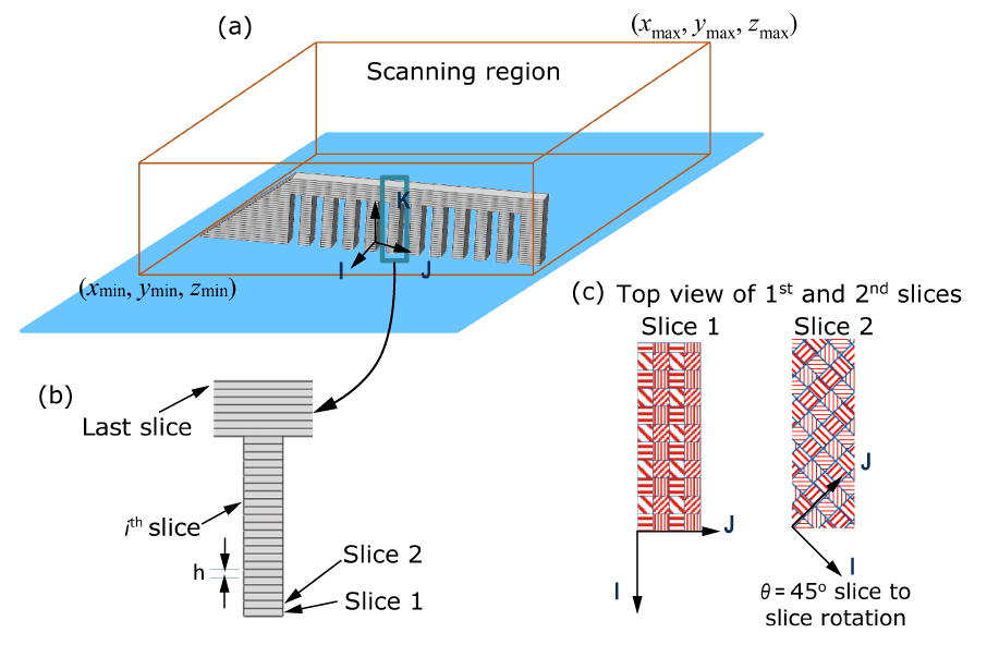
a tool inside a part. The part being printed is divided into equally spaced
(uniform thickness, )
slices or cutting planes that are perpendicular to the build axis,
(see
Figure 1(a)
and
Figure 1(b)).
The build axis system
I–J–K is a
user-defined coordinate system that indicates the printing direction,
K.
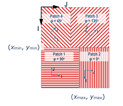
The scan pattern consists of a rectangular unit cell (see
Figure 2).
The rectangular unit cell is repeated to cover the cutting plane. The
rectangular unit cell consists of a number of smaller rectangular patches. Each
patch can define a local angle, ,
between the direction of the scanning motion of the tool and the
I-axis. You can assign an eigenstrain tensor to each of
the pattern patches representing the inelastic deformation induced by the
process. You can define a scan pattern by defining extents of individual
patches (xmin,
ymin) and
(xmax, ymax).
All patches together must form a rectangular unit cell that must be situated
entirely in the first quadrant of the
I–J plane, and one corner of the cell
must be at (0, 0).
A scan pattern is active inside a scanning region. A scanning region is a build axis–oriented bounding box defined by its extent (xmin, ymin, zmin) and (xmax, ymax, zmax) (see Figure 1(a)). The height of a scanning region (zmax–zmin) must be an integral multiple of the thickness, h, of a slice. Multiple nonoverlapping scanning regions can be defined to cover the entire part. A different scan pattern can be active inside each scanning region. All scanning regions share the same build axis system. A layer-to-layer or slice-to-slice rotation angle, , can be defined. The scan pattern is rotated by on the slice for layer (see Figure 1(c)).
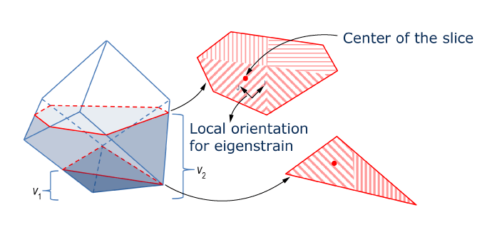
For a given element, the toolpath-mesh intersection module computes the
number of slices, m, inside the element in a given
increment (see
Figure 3).
It finds which pattern patch contains the center of each slice in that element
and the local orientation of that patch considering the layer-to-layer
rotation, ,
and the local rotation, ,
of the scanning direction in that patch. The module also computes the partial
volumes, ,
of the element below each slice.