The problem simulates the process of additive manufacturing of a cube of
dimensions 20.0 × 20.0 × 20.0. The analyses use the special-purpose technique
for pattern-based eigenstrain modeling of additive manufacturing processes in
Abaqus/Standard
(see
Specifying Element Activation and Eigenstrain Using the Pattern-Based Method).
Models using solid elements (C3D8) and shell elements (S4) are tested.
- Model
-
Full element activation is applied to the cube to simulate the
layer-upon-layer material deposition. The material layer thickness (slice
height) is 1.0. A total of 20 layers is needed to build one cube.
- Mesh
-
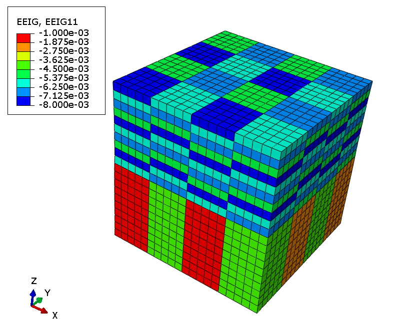
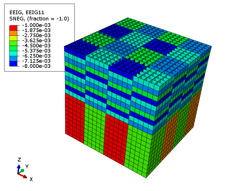
The cube is modeled with a mesh of 20 × 20 × 20 C3D8 elements or a mesh of 16800 S4 elements.
- Material
-
A linear isotropic elastic material is used, with:
| Young's modulus,
|
=10000
|
| Poisson's ratio,
|
=0.33
|
(The units are not important.)
- Loading
-
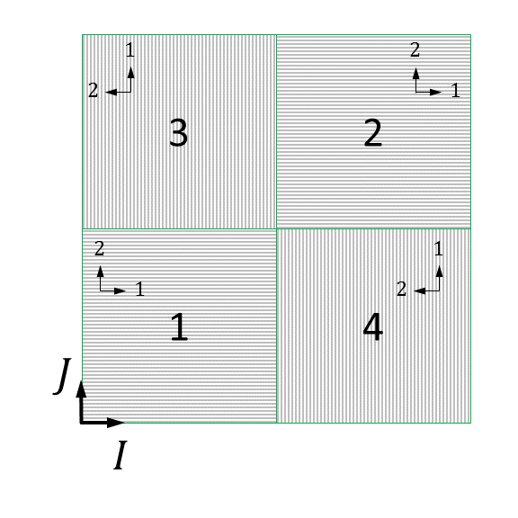
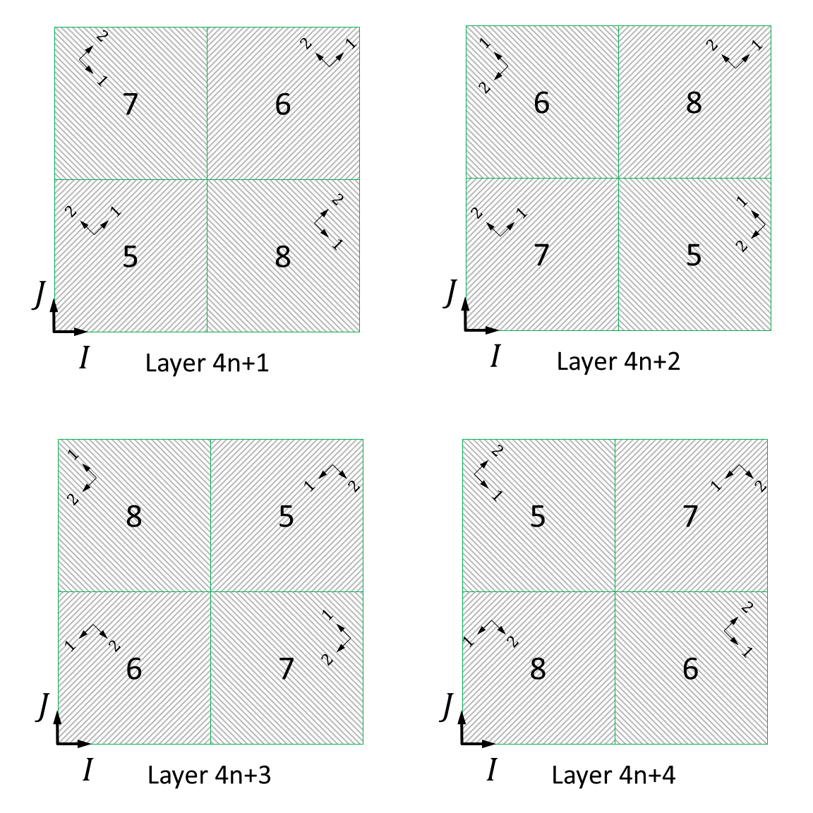
Different scan-pattern strategies are applied to build the lower
half and the upper half of the cube, as shown in
Figure 1
and
Figure 2,
respectively. Each scan pattern consists of four patches. The in-plane
dimensions of all patches are 5.0 × 5.0. For the lower half of the cube the
layer-to-layer (slice-to-slice) rotation of the scan pattern is defined as 0°
about the K-axis of the build system
I-J-K; namely,
the first 10 layers have an identical eigenstrain pattern. The layer-to-layer
rotation angle of the scan pattern of the upper half of the cube is 90°, which
means that the eigenstrain pattern repeats every four layers.
The orientation of the build system
I-J-K is defined
to align with the global orientation
X-Y-Z. The
origin of the build system is at the bottom center of the cube.
Orthotropic eigenstrains are applied on element activation,
.
Table 1
shows the value and the in-plane rotation angle of the eigenstrains for each
patch. For solid elements (for example, C3D8 elements), the material orientation is updated to align with the
rotation angle of the eigenstrain of the patch.
Table 1. Rotation angle and value of eigenstrains of each patch.
| Patch No.
|
Local in-plane rotation
|
Eigenstrain component
|
Eigenstrain component
|
Eigenstrain component
|
| 1
|
0°
|
-0.001
|
-0.001
|
-0.0005
|
| 2
|
0°
|
-0.002
|
-0.002
|
-0.0005
|
| 3
|
90°
|
-0.003
|
-0.003
|
-0.0005
|
| 4
|
90°
|
-0.004
|
-0.004
|
-0.0005
|
| 5
|
45°
|
-0.005
|
-0.005
|
-0.0005
|
| 6
|
45°
|
-0.006
|
-0.006
|
-0.0005
|
| 7
|
-45°
|
-0.007
|
-0.007
|
-0.0005
|
| 8
|
-45°
|
-0.008
|
-0.008
|
-0.0005
|
- Boundary conditions
-
All degrees of freedom of the nodes on the bottom surface of the
cube are fixed.


