Assigning Surface Properties for General Contact in Abaqus/Explicit
Surface property assignments:
can be used to change the contact thickness used for regions of a surface based on
structural elements or to add a contact thickness for regions of a surface based on solid
elements;
can be used to specify surface offsets for regions of a surface based on shell, membrane,
rigid, and surface elements;
can be used to specify which edges of a model should be included in the general contact
domain;
can be used to specify geometric corrections for regions of a surface;
can be used to assign a coordinate system for local tangent directions to the surface
and/or specify preferential frictional directions to the surface in the context of
anisotropic friction;
can be used to assign surface-based friction coefficients, such that friction
coefficients for interactions can be approximated from surface-based friction
coefficients; and
can be applied selectively to particular regions within a general contact domain.
You can assign nondefault surface properties to surfaces involved in general contact
interactions. These properties are considered only when the surfaces are involved in general
contact interactions; they are not considered when the surfaces are involved in other
interactions such as contact pairs. The general contact algorithm does not consider surface
properties specified as part of the surface definition. The regions with nondefault surface
properties are identified with surface names or material names. For example, surface
property SurfProp_A can assign a nondefault surface thickness to
surface Surf_1 or to the surface whose underlying elements have a
section assignment with material Rubber. Material names cannot be
used to assign geometric corrections.
Surface property assignments propagate through all analysis steps in which the general
contact interaction is active.
The surface names used to specify the regions with nondefault surface properties do not
have to correspond to the surface names used to specify the general contact domain. In many
cases the contact interaction will be defined for a large domain, while nondefault surface
properties will be assigned to a subset of this domain. Any surface property assignments for
regions that fall outside the general contact domain will be ignored. The last assignment
will take precedence if the specified regions overlap.
This option must be used in conjunction with the CONTACT option. It should appear at
most once per step for each value of the
PROPERTY parameter discussed below; the
data line can be repeated as often as necessary to assign surface properties to different
regions.
Abaqus/CAE Usage
Interaction module: Create Interaction: General contact (Explicit): Surface Properties
Surface Thickness
The default calculation of the nodal surface thickness (described in detail below), which
remains constant during the simulation, is appropriate for most analyses. For cases in which
changes in the surface thickness may significantly affect contact behavior, Abaqus/Explicit provides options to consider the current thickness (for example, to account for effects
of thinning or thickening of shell thickness) or to consider only thinning effects. You can
specify a value for the surface thickness. For example, you can assign a nonzero thickness
to solid element surfaces to model the effect of a finite-thickness surface coating. Element-Based Surface Definition contains
information on the spatial variation of the surface thickness.
Specifying that original, current, or monotonically decreasing thickness should be used
results in a zero thickness for node-based surfaces. You can specify a nonzero thickness for
a node-based surface used with the general contact algorithm (the contact pair algorithm
will not consider a nonzero thickness for such surfaces).
The general contact algorithm requires that the contact thickness does not exceed a certain
fraction of the surface facet edge lengths or diagonal lengths. This fraction generally
varies from 20% to 60% based on the geometry of the element. The general contact algorithm
scales back the contact thickness automatically where necessary without affecting the
thickness used in the element computations for the underlying elements. Abaqus/Explicit provides diagnostic information in the status (.sta) file if it
performs such scaling.
To bypass this limitation on thickness, you can model the contact surface with surface
elements (see Surface Elements). You must attach
the surface elements to the underlying elements using a surface-based tie constraint (see
Mesh Tie Constraints), and you must
associate a physically reasonable mass with the surface elements. This requires a
significant fraction of the mass to be transferred to the surface elements from the
underlying elements without appreciably altering the bulk mass properties. Alternatively,
you can use contact controls settings to limit the thickness reduction checks (see Contact Controls for General Contact in Abaqus/Explicit).
The “bull-nose” effect that occurs at shell perimeters with the contact pair algorithm (see
Assigning Surface Properties for Contact Pairs in Abaqus/Explicit) is avoided with the general contact
algorithm by default. Shell element edges, nodes, and facets reflect the shell thickness in
the normal direction only and do not extend past the perimeter. You can use contact controls
settings to turn off the bull-nose prevention checks (see Contact Controls for General Contact in Abaqus/Explicit).
Using the Original Parent Element Thickness
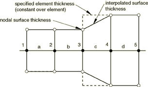
By default, the nodal thickness for surfaces based on shell, membrane, or rigid elements
equals the minimum original thickness of the surrounding elements (see Figure 1 and Table 1). If a node is shared by shell and beam elements, the contact thickness that takes
precedence is the one derived from the shell element. To account for thick beams that are
colocated with shell edges, the beam elements must be attached to the shell edges using a
tie constraint (see Mesh Tie Constraints).
Figure 1. Continuous variation of surface thickness across facet boundaries.
Table 1. Thicknesses corresponding to figure showing continuous variation.
Node
Element
Specified element thickness
Nodal surface thickness (minimum of adjacent
element thicknesses)
1
0.5
a
0.5
2
0.5
b
0.5
3
0.5
c
0.9
4
0.9
d
0.9
5
0.9
The surface thickness within a facet is interpolated from the nodal values; the
interpolated surface thickness never extends past the specified element or nodal
thickness, which may be significant with respect to initial overclosures. The default
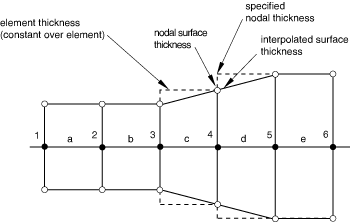
nodal surface thickness is zero for regions of a surface based on solid elements. If a
spatially varying nodal thickness is defined for the underlying elements (see Nodal Thicknesses), the nodal
surface thickness may not correspond exactly to the specified nodal thickness (see node 4
in Figure 2 and Table 2).
Figure 2. Small discrepancy between the nodal surface thickness and the specified nodal
thickness.
Table 2. Thicknesses corresponding to figure showing small discrepancies.
Node
Element
Specified nodal thickness
Element thickness (average of specified nodal
thickness)
Nodal surface thickness (minimum of adjacent
element thicknesses)
1
0.5
0.5
a
0.5
2
0.5
0.5
b
0.5
3
0.5
0.5
c
0.7
4
0.9
0.7
d
0.9
5
0.9
0.9
e
0.9
6
0.9
0.9
The nodal surface thickness distribution will tend to be more diffuse than the specified
nodal thickness distribution (because the specified nodal thicknesses are averaged to
compute the element thicknesses, and the minimum of the surrounding element thicknesses is
the nodal surface thickness).
Input File Usage
SURFACE PROPERTY ASSIGNMENT, PROPERTY=THICKNESSsurface or material, ORIGINAL (default), , SURFACE (default) or MATERIAL
If the first entry is omitted, a default surface that encompasses the entire general
contact domain is assumed.
The fourth entry indicates whether the first entry refers to a surface or material
name. If omitted, Abaqus assumes that a surface name is used.
Abaqus/CAE Usage
Interaction module: Create Interaction: General contact (Explicit): Surface Properties: Surface thickness assignments: Edit:
Select surface or material, click the arrows to transfer surface or material to list of thickness
assignments, and enter ORIGINAL in the Thickness column.
Using the Current Parent Element Thickness
If you specify that the current parent element thickness should be used, increases and
decreases in the parent element thickness are reflected in the contact surface thickness.
An upper bound limiting value for the contact surface thickness remains in effect (based
on a certain fraction of the surface facet edge lengths or diagonal lengths), and the
original surface thickness acts as an upper bound for perimeter nodes except when acting
as main nodes of node-to-surface contact constraints. No lower bound limiting value to the
contact surface thickness exists.
Input File Usage
SURFACE PROPERTY ASSIGNMENT, PROPERTY=THICKNESSsurface or material, CURRENT, , SURFACE (default) or MATERIAL
If you omit the first entry, Abaqus/Explicit assumes a default surface that encompasses the entire general contact domain.
The fourth entry indicates whether the first entry refers to a surface or material
name. If omitted, Abaqus/Explicit assumes that a surface name is used.
Abaqus/CAE Usage
Defining the current parent element thickness is not supported in Abaqus/CAE.
Using the Decreasing Parent Element Thickness
If you specify that the decreasing parent element thickness should be used, only
decreases in the parent element thickness are reflected in the contact surface thickness;
if the parent element thickness actually increases during the analysis, the contact
thickness will remain constant.
Input File Usage
SURFACE PROPERTY ASSIGNMENT, PROPERTY=THICKNESSsurface or material, THINNING, , SURFACE (default) or MATERIAL
If the first entry is omitted, a default surface that encompasses the entire general
contact domain is assumed.
The fourth entry indicates whether the first entry refers to a surface or material
name. If omitted, Abaqus assumes that a surface name is used.
Abaqus/CAE Usage
Interaction module: Create Interaction: General contact (Explicit): Surface Properties: Surface thickness assignments: Edit:
Select surface or material, click the arrows to transfer surface or material to list of thickness
assignments, and enter THINNING in the Thickness column.
Specifying a Value for the Surface Thickness
You can directly specify the surface thickness value.
If the first entry is omitted, a default surface that encompasses the entire general
contact domain is assumed.
The fourth entry indicates whether the first entry refers to a surface or material
name. If omitted, Abaqus assumes that a surface name is used.
Abaqus/CAE Usage
Interaction module: Create Interaction: General contact (Explicit): Surface Properties: Surface thickness assignments: Edit:
Select surface or material, click the arrows to transfer surface or material to list of thickness
assignments, and enter a value for the surface thickness magnitude in the Thickness column.
Applying a Scale Factor to the Surface Thickness
You can apply a scale factor to any value of the surface thickness. For example, if you
specify that the decreasing parent element thickness should be used for
surf1 and apply a scale factor of 0.5, a value of one half
the decreasing parent element thickness will be used for
surf1 when it is involved in a general contact interaction
(all other surfaces included in the general contact domain will use the default original
parent element thickness). Scaling the surface thickness in this way can be used to avoid
initial overclosures in some situations. Abaqus/Explicit will automatically adjust surface positions to resolve initial overclosures (see Contact Initialization for General Contact in Abaqus/Explicit). However, if nodal position adjustments are
undesirable (for example, if they would introduce an imperfection in an otherwise flat
part, resulting in an unrealistic buckling mode), you may prefer to reduce the surface
thickness and avoid the overclosures entirely.
Input File Usage
SURFACE PROPERTY ASSIGNMENT, PROPERTY=THICKNESSsurface or material, value or label, scale_factor, SURFACE (default) or MATERIAL
If the first entry is omitted, a default surface that encompasses the entire general
contact domain is assumed.
The fourth entry indicates whether the first entry refers to a surface or material
name. If omitted, Abaqus assumes that a surface name is used.
Abaqus/CAE Usage
Interaction module: Create Interaction: General contact (Explicit): Surface Properties: Surface thickness assignments: Edit:
Select surface or material, click the arrows to transfer surface or material to list of thickness
assignments, and enter a Scale Factor.
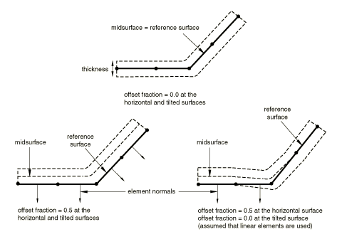
Surface Offset
A surface offset is the distance between the midplane of a thin body and its reference
plane (defined by the nodal coordinates and element connectivities). It is computed by
multiplying the offset fraction (specified as a fraction of the surface thickness) by the
surface thickness and the element facet normal. This defines the position of the midsurface
and, thus, the position of the body with respect to the reference surface; the coordinates
of the nodes on the reference surface are not modified. Surface offsets can be specified
only for surfaces defined on shell and similar elements (i.e., membrane, rigid, and surface
elements). Surface offsets specified for other elements (e.g., solid or beam elements) will
be ignored. By default, surface offsets specified in element section definitions will be
used in the general contact algorithm.
The surface offset at each node is the average of the maximum and minimum offsets among the
faces connected to the node. The offset at a point within a facet is interpolated from the
nodal values. Figure 3 shows some examples of the positioning of the contact surface with respect to the
reference surface for various combinations of surface offsets. Surface offsets used in the
general contact algorithm are constrained to lie between −0.5 and 0.5 of the thickness.
You specify the surface offset as a fraction of the surface thickness. The surface offset
fraction can be set equal to the offset fraction used for the surface's parent elements or
to a specified value. Surface offsets specified for general contact do not change the
element integration.
Figure 3. Specifying surface offsets for general contact.
Input File Usage
Use the following option to use the surface offset fraction from the surface's parent
elements (default):
SURFACE PROPERTY ASSIGNMENT, PROPERTY=OFFSET FRACTIONsurface or material, ORIGINAL, SURFACE (default) or MATERIAL
Use the following option to specify a value for the surface offset fraction:
SURFACE PROPERTY ASSIGNMENT, PROPERTY=OFFSET FRACTIONsurface or material, offset, SURFACE (default) or MATERIAL
The offset can be specified as a value or a label
(SPOS or SNEG).
Specifying SPOS is equivalent to specifying a value of
0.5; specifying SNEG is equivalent to specifying a value
of −0.5.
The third entry indicates whether the first entry refers to a surface or material
name. If omitted, Abaqus assumes that a surface name is used.
Abaqus/CAE Usage
Interaction module: Create Interaction: General contact (Explicit): Surface Properties: Shell/Membrane offset assignments: Edit:
Select surface or material, and click the arrows to transfer surface or material to list of offset
assignments.
In the Offset Fraction column, enter ORIGINAL to use the surface offset fraction from the surface's parent elements, enter SPOS to use a surface offset fraction of 0.5, enter SNEG to use a surface offset fraction of −0.5, or enter a value for the surface offset fraction.
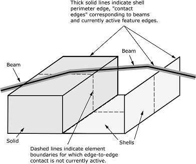
Feature Edges
Feature edges of a model are defined on beam and truss elements and edges of faces
(perimeter and otherwise) of solid and structural elements. Feature edges, such as shown in
Figure 4, can
participate in edge-to-edge contact in Abaqus/Explicit (see Surfaces Used for General Contact). Figure 4. General contact domain, including edge-to-edge contact.
By default in Abaqus/Explicit:
“Contact edges” of beam and truss elements and perimeter edges of shells and membranes
act as primary feature edges (see Primary and Secondary Feature Edges), as long as the underlying elements remain active.
Feature angle thresholds of 30° for primary feature edges and 20° for secondary feature
edges are applied dynamically throughout a simulation to determine which edges of solid
elements and which non-perimeter edges of shell elements currently act as primary or
secondary feature edges. The feature angle is the angle formed between the normal
directions of the two facets connected to an edge, as discussed further in The Feature Angle. As an edge’s
feature angle evolves during a simulation, its classification as a primary feature edge,
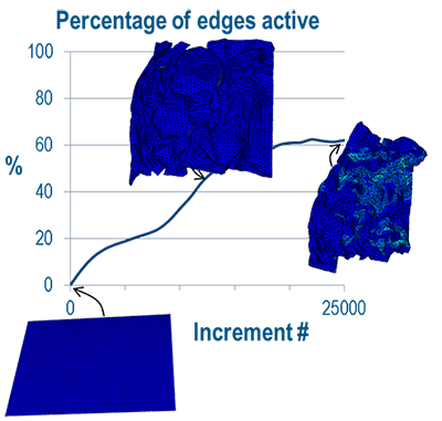
a secondary feature edge, or not a feature edge may also change. Figure 5 shows a crumpling example in which many feature edges form during a
simulation. Other types of simulations (such as airbag deployment) involve many feature
edges unfolding over the course of a simulation.
Figure 5. Percentage of active edges versus increment number for a paper crumpling example:
original (flat sheet), intermediate, and final configurations.
Input File Usage
By default, Abaqus/Explicit automatically applies evolving feature edge criteria to the entire contact domain,
including all structural and solid elements. This is equivalent to the following
definition:
SURFACE PROPERTY ASSIGNMENT, PROPERTY=FEATURE EDGE CRITERIAsurface or material,,,, CURRENT,, SURFACE (default) or MATERIAL
The seventh entry indicates whether the first entry refers to a surface or material
name. If omitted, Abaqus assumes that a surface name is used.
Abaqus/CAE Usage
Interaction module: Create Interaction: General contact (Explicit): Surface Properties: Feature edge criteria assignments: Edit: select surface or material and the configuration CURRENT in the columns on the left, and click the arrows to transfer the surface or material to the list of feature assignments.
Using a Fixed Set of Active Feature Edges for Contact Based on Original Feature
Angles
Optionally, Abaqus/Explicit can establish a fixed set of active feature edges for contact based on original feature
angles. If no feature angle thresholds are specified explicitly, the list of active
feature edges matches the default initially active feature edges for dynamically applied
criteria (30° for primary feature edges and 20° for secondary feature edges), but this
list is not updated during the simulation. This option is not well suited for common
scenarios involving significant deformation during a simulation. However, using a fixed
set of active feature edges can save computational time for simulations involving small
deformation.
Input File Usage
Use the following option to apply the feature edge criteria only at the beginning of
the simulation such that the list of active feature edges for contact remains
constant:
SURFACE PROPERTY ASSIGNMENT, PROPERTY=FEATURE EDGE CRITERIAsurface or material,,,, ORIGINAL,, SURFACE (default) or MATERIAL
The seventh entry indicates whether the first entry refers to a surface or material
name. If omitted, Abaqus assumes that a surface name is used.
Abaqus/CAE Usage
Interaction module: Create Interaction: General contact (Explicit): Surface Properties: Feature edge criteria assignments: Edit:
Select the surface or material and the configuration ORIGINAL in the columns on the left, and click the arrows to transfer the surface or material to the list of feature
assignments.
Limiting Feature Edges to Perimeter Edges and Contact Edges of Beams and
Trusses
You can limit feature edges for edge-to-edge contact to perimeter edges and contact edges
of beams and trusses. Perimeter edges occur on “physical” perimeters of shell elements and
on “artificial” edges that occur when a subset of exposed facets on a body are included in
the general contact domain. When structural elements share nodes with continuum elements,
the perimeter edges are not activated on the structural elements because the criterion to
designate them as such is no longer satisfied.
Input File Usage
SURFACE PROPERTY ASSIGNMENT, PROPERTY=FEATURE EDGE CRITERIAsurface or material, PERIMETER EDGES (default),,,,, SURFACE (default) or MATERIAL
If the first entry is omitted, a default surface that encompasses the entire general
contact domain is assumed.
The seventh entry indicates whether the first entry refers to a surface or material
name. If omitted, Abaqus assumes that a surface name is used.
Abaqus/CAE Usage
Interaction module: Create Interaction: General contact (Explicit): Surface Properties: Feature edge criteria assignments: Edit:
Select surface or material, click the arrows to transfer surface or material to list of feature
assignments, and enter PERIMETER in the Primary Feature Edge Criteria column.
Specifying Particular Feature Edges to Be Activated
You can choose particular feature edges on surface, structural, and rigid elements to be
activated in domain. A surface containing a list of element labels and edge identifiers
(see “Defining edge-based surfaces” in Element-Based Surface Definition) is used to
specify the edges to activate.
Input File Usage
SURFACE PROPERTY ASSIGNMENT, PROPERTY=FEATURE EDGE CRITERIAsurface or material, PICKED EDGES,,,,, SURFACE (default) or MATERIAL
The seventh entry indicates whether the first entry refers to a surface or material
name. If omitted, Abaqus assumes that a surface name is used.
Abaqus/CAE Usage
Interaction module: Create Interaction: General contact (Explicit): Surface Properties: Feature edge criteria assignments: Edit:
Select the surface or material, click the arrows to transfer the surface or material to the list of feature
assignments, and enter PICKED in the Primary Feature Edge Criteria column.
Specifying That All Feature Edges Should Be Activated
You can choose to activate all edges each increment in a given surface in the general
contact domain. However, this option degrades performance.
Input File Usage
Use the following option to force all edges to be considered each increment:
SURFACE PROPERTY ASSIGNMENT, PROPERTY=FEATURE EDGE CRITERIAsurface or material, ALL EDGES,,, ORIGINAL,, SURFACE (default) or MATERIAL
The seventh entry indicates whether the first entry refers to a surface or material
name. If omitted, Abaqus assumes that a surface name is used.
Abaqus/CAE Usage
Interaction module: Create Interaction: General contact (Explicit): Surface Properties: Feature edge criteria assignments: Edit:
Select the surface or material, click the arrows to transfer the surface or material to the list of feature
assignments, and enter ALL in the Primary Feature Edge Criteria column.
Specifying That All Feature Edges Should Be Deactivated
You can choose to deactivate all feature edges (including perimeter edges) in the general
contact domain. This option does not deactivate “contact edges” associated with beam and
truss elements.
Input File Usage
SURFACE PROPERTY ASSIGNMENT, PROPERTY=FEATURE EDGE CRITERIAsurface or material, NO FEATURE EDGES,,,,, SURFACE (default) or MATERIAL
If the first entry is omitted, a default surface that encompasses the entire general
contact domain is assumed.
The seventh entry indicates whether the first entry refers to a surface or material
name. If omitted, Abaqus assumes that a surface name is used.
Abaqus/CAE Usage
Interaction module: Create Interaction: General contact (Explicit): Surface Properties: Feature edge criteria assignments: Edit:
Select the surface or material, click the arrows to transfer the surface or material to the list of feature
assignments, and enter NONE in the Primary Feature Edge Criteria column.
Specifying a Cutoff Feature Angle
If you specify a cutoff feature angle as the feature edge criteria, perimeter edges and
geometric edges with feature angles greater than or equal to the specified angle are
activated in the general contact domain. By default, the feature angle thresholds are
applied dynamically throughout the simulation. Optionally, you can specify that the
feature angle thresholds are applied only once at the beginning of the analysis. As
described previously, you can activate additional feature edges if required.
Input File Usage
SURFACE PROPERTY ASSIGNMENT, PROPERTY=FEATURE EDGE CRITERIAsurface or material, feature_angle_value,,,,, SURFACE (default) or MATERIAL
If the first entry is omitted, a default surface that encompasses the entire general
contact domain is assumed.
The fifth entry indicates how to apply the feature angle thresholds: CURRENT to
apply them throughout the simulation (default) or ORIGINAL to apply them only once at
the beginning of the analysis.
The seventh entry indicates whether the first entry refers to a surface or material
name. If omitted, Abaqus assumes that a surface name is used.
Abaqus/CAE Usage
Interaction module: Create Interaction: General contact (Explicit): Surface Properties: Feature edge criteria assignments: Edit:
Select surface or material, click the arrows to transfer surface or material to list of feature
assignments, and enter a value for the cutoff feature angle (in degrees) in the Primary Feature Edge Criteria column.
Example: Assigning Different Feature Edge Criteria to Different Regions
You can assign a different feature edge criteria to different regions of the general
contact domain. For example, Table 3and Table 4 show the
input that could be used to specify that none of the feature edges of
surf1, only perimeter edges of
surf2, and perimeter edges and feature edges of
surf3 with a feature angle greater than 30° should be
considered for edge-to-edge contact.
To reduce computational cost in certain situations, it may be desirable to specify two
feature angle criteria for a given surface. Edges satisfying the more restrictive criteria
are considered primary feature edges, and edges satisfying the less restrictive criteria
only are considered secondary feature edges. If primary and secondary feature edge
criteria are in effect, Abaqus/Explicit enforces edge-to-edge contact between primary feature edges and between primary feature
edges and secondary feature edges only. Edge-to-edge contact is not enforced between
secondary feature edges. This ensures that interpenetrations are avoided at locations
where there are “true” edges in the model, without the need to activate primary feature
edges at locations where the gradients in the surface normals are only moderate. A
judicious choice of criteria for selecting primary and secondary feature edges can lead to
significant savings in computational costs.
Secondary feature edges can be selected for a surface by specifying a secondary feature
edge criterion in addition to the criterion used to select the primary feature edges for
that surface. If the secondary feature edge criterion is omitted, only primary feature
edges are activated for the surface. Allowable criteria for secondary feature edges are:
all edges that have not been selected as primary feature edges;
all picked edges that have not been selected as primary feature edges;
all perimeter edges that have not been selected as primary feature edges; and
all edges with a feature angle greater than a specified cutoff angle value that have
not been selected as primary feature edges.
The allowable values for the secondary feature edge criterion permit possible
combinations of criteria for primary feature edges and secondary feature edges, shown in
Table 5.
Table 5. Valid combinations of primary feature edge and secondary feature edge
criteria.
Primary Feature Edge Criterion
Secondary Feature Edge Criterion
No feature edges
All remaining edges, picked edges, perimeter edges, cutoff angle
All edges
Any criterion specified for secondary feature edges will be ignored
Picked edges
All remaining edges, perimeter edges, cutoff angle
Perimeter edges
All remaining edges, picked edges, cutoff angle
Cutoff angle
All remaining edges, picked edges, perimeter edges, cutoff angle
Specifying All Remaining Edges as Secondary Feature Edges
You can specify that all edges belonging to the surface that have not been selected as
primary feature edges become secondary feature edges.
Input File Usage
SURFACE PROPERTY ASSIGNMENT, PROPERTY=FEATURE EDGE CRITERIAsurface or material, primary feature edge criterion, ALL REMAINING EDGES,,,, SURFACE (default) or MATERIAL
If the first entry is omitted, a default surface that encompasses the entire
general contact domain is assumed.
The seventh entry indicates whether the first entry refers to a surface or
material name. If omitted, Abaqus assumes that a surface name is used.
Abaqus/CAE Usage
Interaction module: Create Interaction: General contact (Explicit): Surface Properties: Feature edge criteria assignments: Edit:
Select the surface or material, click the arrows to transfer the surface or material to the list of feature
assignments, and enter ALL in the Secondary Feature Edge Criteria column.
Specifying Picked Edges as Secondary Feature Edges
You can specify that all picked edges of the surface that have not already been
selected as primary feature edges become secondary feature edges.
Input File Usage
SURFACE PROPERTY ASSIGNMENT, PROPERTY=FEATURE EDGE CRITERIAsurface or material, primary feature edge criterion, PICKED EDGES,,,, SURFACE (default) or MATERIAL
If the first entry is omitted, a default surface that encompasses the entire
general contact domain is assumed.
The seventh entry indicates whether the first entry refers to a surface or
material name. If omitted, Abaqus assumes that a surface name is used.
Abaqus/CAE Usage
Interaction module: Create Interaction: General contact (Explicit): Surface Properties: Feature edge criteria assignments: Edit:
Select the surface or material, click the arrows to transfer the surface or material to the list of feature
assignments, and enter PICKED in the Secondary Feature Edge Criteria column.
Specifying Perimeter Edges as Secondary Feature Edges
You can specify that all perimeter edges of the surface that have not already been
selected as primary feature edges become secondary feature edges.
Input File Usage
SURFACE PROPERTY ASSIGNMENT, PROPERTY=FEATURE EDGE CRITERIAsurface or material, primary feature edge criterion, PERIMETER EDGES,,,, SURFACE (default) or MATERIAL
If the first entry is omitted, a default surface that encompasses the entire
general contact domain is assumed.
The seventh entry indicates whether the first entry refers to a surface or
material name. If omitted, Abaqus assumes that a surface name is used.
Abaqus/CAE Usage
Interaction module: Create Interaction: General contact (Explicit): Surface Properties: Feature edge criteria assignments: Edit:
Select surface or material, click the arrows to transfer surface or material to list of feature
assignments, and enter PERIMETER in the Secondary Feature Edge Criteria column.
Specifying a Cutoff Feature Angle for Secondary Feature Edges
You can specify that edges on the surface with a feature angle greater than the
specified value that have not been selected as primary feature edges become secondary
feature edges. If an angle value has also been specified for primary feature edges, the
angle value specified for secondary feature edges must be smaller than the value
specified for primary edges.
Input File Usage
SURFACE PROPERTY ASSIGNMENT, PROPERTY=FEATURE EDGE CRITERIAsurface or material, primary feature edge criterion, feature_angle_value,,,, SURFACE (default) or MATERIAL
If the first entry is omitted, a default surface that encompasses the entire
general contact domain is assumed.
The seventh entry indicates whether the first entry refers to a surface or
material name. If omitted, Abaqus assumes that a surface name is used.
Abaqus/CAE Usage
Interaction module: Create Interaction: General contact (Explicit): Surface Properties: Feature edge criteria assignments: Edit:
Select surface or material, click the arrows to transfer surface or material to list of feature
assignments, and enter a value for the cutoff feature angle (in degrees) in the Secondary Feature Edge Criteria column.
Specifying That Edges Are Activated Only as Secondary Feature Edges
For a particular surface you may not want to activate any primary feature edges;
instead, you might want to activate all or some edges on the surface as secondary
feature edges (to enforce contact between these secondary feature edges and primary
feature edges on another surface in the model). In that case you can specify that no
feature edges should be activated as the primary feature edge criterion for the surface,
while using any criterion of choice for the secondary feature edges.
Input File Usage
SURFACE PROPERTY ASSIGNMENT, PROPERTY=FEATURE EDGE CRITERIAsurface or material, NO FEATURE EDGES, secondary feature edge criterion,,,, SURFACE (default) or MATERIAL
If the first entry is omitted, a default surface that encompasses the entire
general contact domain is assumed.
The seventh entry indicates whether the first entry refers to a surface or
material name. If omitted, Abaqus assumes that a surface name is used.
Abaqus/CAE Usage
Interaction module: Create Interaction: General contact (Explicit): Surface Properties: Feature edge criteria assignments: Edit:
Select the surface or material, click the arrows to transfer the surface or material to the list of feature
assignments, and enter NONE in the Secondary Feature Edge Criteria column.
The Feature Angle
The feature angle is the angle formed between the normals of the two facets connected to
an edge. By default, the angles between facets are based on the initial configuration.
However, the most efficient approach for accurately resolving contact is often to apply
the feature edge criteria to the current configuration. In this case the edges that are
eligible for edge-to-edge contact evolve during the simulation.
A negative angle will result at concave meetings of facets; therefore, these edges are
not included in the contact domain if the feature edge criteria is based on a cutoff
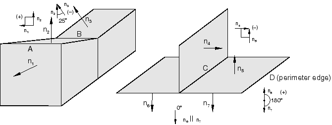
feature angle. Figure 6 shows some examples of how the feature angle is calculated for
different edges.
Figure 6. Calculating the feature angle.
The feature angle for edge A is 90° (the angle between and ); the feature angle for edge B is −25° (the angle between and ). Edge C forms a T-intersection with three facets (shown in two
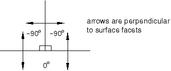
dimensions in Figure 7); its feature angles are 0°, −90°, and −90°.
Figure 7. Feature angles for a T-intersection.
Perimeter edges (for example, edge D in Figure 6) can
be thought of as a special type of feature edge where the feature angle is 180°.
The sign of the feature angle is considered when determining whether or not a geometric
feature edge should be activated in the general contact domain. For example, if a cutoff
feature angle of 20° were specified, edge A would be activated as a feature edge in the
contact model (90° > 20°) but edges B and C would not be activated: −25° < 20° and
0° (the maximum feature angle for edge C) < 20°.
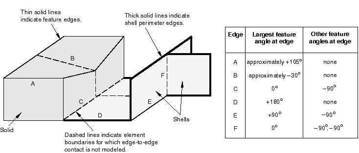
Figure 8
illustrates further how the feature angle is used to determine which geometric feature
edges should be activated in the general contact domain.
Figure 8. Feature edges activated in the general contact domain for a cutoff feature angle of
20°.
The table to the right of the figure lists the feature angle values for various edges in
the model. Edges connected to more than two facets, as well as edges connected to two
shell facets, have more than one corresponding feature angle. The largest feature angle at
an edge is compared to the specified cutoff feature angle. For example, if a cutoff
feature angle of 20° were specified, edges A, D, and E would be considered feature edges,
while edges B, C, and F would be ignored for edge-to-edge contact.
Output
The contact output variable
CEDGEACTIVE
is available to identify throughout the analysis if an edge is active as a primary edge,
active as a secondary edge, or has been deactivated by the contact domain.
Surface Geometry Correction
By default, contact calculations are based on unsmoothed, faceted representations of the
finite element surfaces in a general contact domain. Discrepancies between the true surface
geometry and the faceted surface geometry may result in significant noise in the solution.
Optional contact smoothing techniques simulate a more realistic representation of curved
surfaces in the contact calculations. These techniques allow a discretized surface with
discontinuous surface normals to more closely approximate the behavior of a smooth surface
during an analysis. Improvements to results with the surface correction include more
accurate contact stresses and less solution noise upon relative sliding between contact
surfaces.
Contact smoothing can be specified for surfaces in a general contact domain using a surface
property assignment. A single surface property assignment specifies all of the surfaces to
be smoothed, as well as the appropriate geometry correction method for each surface. Three
geometry correction methods can be employed:
The circumferential smoothing method is applicable to surfaces approximating a portion
of a surface of revolution.
The spherical smoothing method is applicable to surfaces approximating a portion of a
sphere.
The toroidal smoothing method is applicable to surfaces approximating a portion of a
torus (i.e., a circular arc revolved about an axis).
For each surface, you must specify the appropriate geometry correction method and either
the approximate axis of revolution (for circumferential or toroidal smoothing) or the
approximate spherical center (for spherical smoothing). For toroidal smoothing, you must
also specify the distance of the center of the circular arc from the axis of revolution. The
center of the circular arc is then located such that the line it forms with point
(Xa, Ya, Za) is perpendicular with the axis of revolution.
Input File Usage
Use the following option to apply a geometric correction and define the parameters by
specifying coordinates:
SURFACE PROPERTY ASSIGNMENT, PROPERTY=GEOMETRIC CORRECTION, DEFINITION=COORDINATESdata lines to define smoothing regions
Several examples for data line entries are shown below. Repeat the data lines as many
times as necessary to define the appropriate geometry corrections for all surfaces in the
contact domain.
To apply circumferential smoothing to a surface with an axis of symmetry passing
through points (Xa, Ya, Za) and (Xb,
Yb, Zb):
surface, CIRCUMFERENTIAL, Xa, Ya, Za, Xb, Yb, Zb
To apply spherical smoothing to a surface with a spherical center at point
(Xa, Ya, Za):
surface, SPHERICAL, Xa, Ya, Za
To apply toroidal smoothing to a surface with an axis of symmetry passing through
points (Xa, Ya, Za) and (Xb, Yb,
Zb) with the center of the revolved circular arc at a distance
R from the axis of symmetry:
surface, TOROIDAL, Xa, Ya, Za, Xb, Yb, Zb, R
Use the following option to apply a geometric correction and define the parameters by
specifying nodes:
SURFACE PROPERTY ASSIGNMENT, PROPERTY=GEOMETRIC CORRECTION, DEFINITION=NODESdata lines to define smoothing regions
Several examples for data line entries are shown below. Repeat the data lines as many
times as necessary to define the appropriate geometry corrections for all surfaces in the
contact domain.
To apply circumferential smoothing to a surface with an axis of symmetry passing
through nodes a and b:
surface, CIRCUMFERENTIAL, node a, node b
To apply spherical smoothing to a surface with a spherical center at node a:
surface, SPHERICAL, node a
To apply toroidal smoothing to a surface with an axis of symmetry passing through
nodes a and b with the center of the revolved circular arc at a distance
R from the axis of symmetry:
surface, TOROIDAL, node a, node b, R
Abaqus/CAE Usage
Contact surface smoothing can be applied only to native geometry models in Abaqus/CAE. Abaqus/CAE can automatically detect all circumferential, spherical, and toroidal surfaces in the
general contact domain that can be smoothed and apply the appropriate smoothing.
Use the following option to enable automatic surface smoothing of a model:
Interaction module: Create Interaction: General contact (Explicit): Surface Properties: Surface smoothing assignments: Edit:
toggle on Automatically assign smoothing for geometric faces
Use the following option to manually apply smoothing to a surface:
Interaction module: Create Interaction: General contact (Explicit): Surface Properties: Surface smoothing assignments: Edit:
Select the surface, click the arrows to transfer the surface to the list of smoothing
assignments.
In the Smoothing Option column, select REVOLUTION to apply circumferential smoothing, select SPHERICAL to apply spherical smoothing, select TOROIDAL to apply toroidal smoothing, or select NONE to prevent smoothing of the surface.
Considerations for Geometric Correction
The contact smoothing technique assumes that the initial locations of the surface nodes
lie on the true initial surface geometry, with the exception of midedge nodes of
C3D10M elements. This smoothing technique
remains effective even if the midedge nodes of
C3D10M elements do not lie on the true
initial geometry (models meshed using Abaqus/CAE always have midedge nodes placed on the true initial geometry, but this may not be the
case with other meshing preprocessors).
The effects of contact smoothing tend to be most significant for analyses involving small
deformation, and the smoothing technique works well for cases involving large relative
motion between the surfaces. For analyses with large deformation this smoothing technique
typically has an insignificant effect on the solution. However, in some cases—especially
where the underlying elements can fail—the smoothing can degrade the solution accuracy
after large deformation.
Effects of Geometric Correction
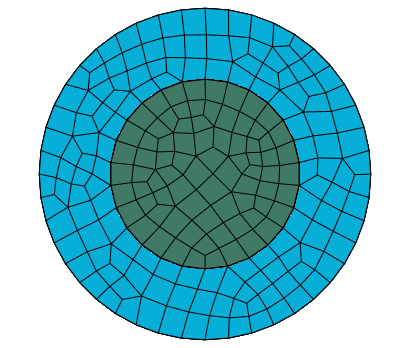
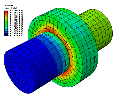
The impact of contact surface smoothing can be demonstrated by a simple model of contact
between concentric cylinders with a small clearance between them. With a matched mesh as
shown in Figure 9 there are no initial overclosures; therefore, there are no initial strain-free initial
displacement adjustments. However, if the inner cylinder is rotated, the cylinders develop
stresses (see Figure 10) as contact is detected due to the linear faceted representation of the main surface.
This behavior is improved when the circumferential smoothing technique is applied to the
contacting surfaces of the two cylinders.
Figure 9. Concentric cylinders with matched mesh. Figure 10. Stresses as cylinder rotates.
Surface-Based Friction Coefficients
In Abaqus/Explicit you can establish friction coefficients as mathematical combinations of coefficients
specified as surface properties (see Deriving Friction Coefficients from Quantities Specified as Surface Properties). For
contact between surfaces with identical surface-based coefficients, the function to compute
the friction coefficient for an interface returns the same coefficient; otherwise, this
function returns a coefficient between the two surface-based coefficients and closer to the
lower of the surface-based coefficients. See Deriving Friction Coefficients from Quantities Specified as Surface Properties for
more details about this capability, including user control of the function for computing
interaction friction coefficients for surface-based friction coefficients.
Input File Usage
Use the following option to assign surface-based friction coefficients:
SURFACE PROPERTY ASSIGNMENT, PROPERTY=FRICTIONsurface or material, friction_coefficient, SURFACE (default) or MATERIAL
The third entry indicates whether the first entry refers to a surface or material
name. If omitted, Abaqus assumes that a surface name is used.
Abaqus/CAE Usage
Interaction module: Create Interaction: General contact (Explicit): Surface Properties: Surface friction assignments: Edit:
Select surface or material, click the arrows to transfer surface or material to list of friction
assignments, and enter a value for the friction coefficient in the Friction Coefficient column.
Orientations
For surface regions, you can specify
the initial orientation of local tangent
directions and/or
the degree of frictional directional preference
for the local versus tangent directions in the context of an anisotropic friction model.
For each surface region, you can refer to a named orientation system and, if desired, an
extra rotation (in degrees) applied to the orientation system once it has been projected to
the surface. If no orientations are specified or an analytical rigid surface is used, Abaqus initializes the contact directions using the standard convention (see Conventions).
The specified local coordinate system is associated with a surface; whereas, the local
tangent directions discussed in Local Tangent Directions for Contact are associated with contact constraints. The local coordinate system for contact is
inherited from one of the surfaces, as discussed in Local Tangent Directions for Contact.
A preferred frictional direction for a surface in conjunction with anisotropic friction
behavior can be specified using a frictional directional preference factor (default) or a frictional directional preference ratio
r (see Anisotropic Friction with Directional Preference as a Surface Property).
Input File Usage
Use the following option to define a preferred contact orientation:
SURFACE PROPERTY ASSIGNMENT, PROPERTY=ORIENTATIONsurface or material, orientation_system, extra_rotation_angle,, SURFACE (default) or MATERIAL
The fifth entry indicates whether the first entry refers to a surface or material
name. If omitted, Abaqus assumes that a surface name is used.
Use the following option to define the frictional directional preference factor :
Defining a preferred contact orientation, frictional directional preference factor,
and ratio of friction coefficients is not supported in Abaqus/CAE.
Preferred Fraction of Frictional Work Directed to a Surface as a Surface Property
In Abaqus/Explicit you can specify the preferred fraction of frictional work of an interaction directed to a
surface as a surface property. The default fraction is 0.5, which directs half of the
friction work of an interaction to each surface. If the preferred fractions of the surfaces
in an interaction do not sum to unity, a normalization process occurs in the context of the
interaction such that the actual frictional work distribution fractions for that interaction
sum to unity. This normalization process is described by the following equations:
Frictional work distribution factors influence the nodal frictional work output
but have no influence on the distribution of heat associated with friction to the respective
interacting surfaces, which can be influenced with pre-existing gap heat generation controls
(Modeling Heat Generated by Nonthermal Surface Interactions).
Input File Usage
Use the following option to assign surface-based friction work distributions:
SURFACE PROPERTY ASSIGNMENT, PROPERTY=DISTRIBUTION FACTORsurface or material, preferred fraction (between 0.0 and 1.0), SURFACE (default) or MATERIAL
The third entry indicates whether the first entry refers to a surface or material
name. If omitted, Abaqus assumes that a surface name is used.
Abaqus/CAE Usage
Assigning preferred fractions of frictional work is not supported in Abaqus/CAE.