Abaqus/Standard provides a cavity radiation capability for modeling heat transfer effects due to radiation
in enclosures. This cavity radiation functionality:
is provided for two-dimensional, three-dimensional, and axisymmetric cases;
accounts for symmetries, surface blocking, and surface motion within cavities; and
can include closed cavities or open cavities (implying that some radiation takes place to
an exterior medium).
Cavity radiation equations are not symmetric; therefore, the nonsymmetric matrix storage and
solution scheme is invoked automatically in models that include cavity radiation (see Cavity radiation and Defining an Analysis). Each cavity
defines a view factor matrix involving the geometric relations between the surfaces in the
enclosure. These matrices may be updated a number of times during the analysis (due to moving
surfaces in the cavity). Therefore, large cavity radiation problems may be computationally
expensive. Instead, you should consider using:
average-temperature radiation conditions for modeling enclosures that are approximately
isothermal, with constant emissivity, and do not require blocking or reflection
considerations (see Thermal Loads); or
parallel cavity decomposition for parallel calculation of view factors and solution of
the radiative heat transfer equations (see Decomposing Large Cavities in Parallel below).
Since cavity radiation effects are calculated only in heat transfer and coupled
thermal-electrical procedures, the only kind of thermal-stress analysis that can include
these effects is sequentially coupled thermal-stress analysis (see Sequentially Coupled Thermal-Stress Analysis). Moreover,
unless you allow cavity parallel decomposition (see Decomposing Large Cavities in Parallel below), there is
a software limit of 16,000 nodes and facets in Abaqus/Standard. In addition, there is a limit that you can define at most 100 cavities in a single
analysis.
Model Definition
When you define the model for a cavity radiation problem, you must:
In the first step of a cavity radiation analysis you must associate with each cavity a
radiation view factor definition, which controls the calculation of view factors for the
cavity. You then may:
define boundary conditions such as temperature and forced convection (see Boundary Conditions);
control the cavity radiation and view factor calculations in each step (the
specifications from the previous step are used if they are not redefined in a step;
see Controlling View Factor Calculation during the Analysis);
If any of the above are included in your analysis, they must be defined within a heat
transfer or coupled thermal-electrical step definition.
Defining Surfaces
Cavities are defined in Abaqus/Standard as collections of surfaces, which are composed of facets. In axisymmetric and
two-dimensional cases a facet is a side of an element; in three-dimensional cases a facet is
a face of a solid element or a surface of a shell element. Rigid surfaces cannot be used in
cavity radiation problems.
Surfaces are defined as described in Element-Based Surface Definition. You may
associate each surface with a surface property definition as part of the surface option, or
you may associate surfaces with surface properties as part of the cavity definition option.
The surface properties are defined as described below.
Input File Usage
Use the following option to define a surface with a surface property for use in a
cavity radiation analysis:
Use the following option to define a surface for use in a cavity radiation analysis in
which surface properties are defined as part of the cavity definition:
Interaction module: Create Interaction: Cavity radiation: select the initial surface region
Restrictions
Surfaces that are associated with cavity radiation are subject to the following
restrictions in addition to the general surface definition restrictions outlined in Element-Based Surface Definition:
Surfaces cannot overlap because of the ambiguity that would result in the associated
property definitions and in the blocking specification.
A surface can be used only in one cavity definition (the same surface cannot appear
in two different cavities).
In addition, the three-dimensional quadrilateral facets should be as close to planar as
possible; otherwise, the quality of the view factor calculations will be compromised.
Controlling Spurious Spatial Oscillations
The radiation flux for each facet is calculated based on the average of the nodal
temperatures on that facet (see Cavity radiation). This value
of radiation flux is then distributed to each node in proportion to its area.
Consequently, the mesh must be sufficiently fine that temperature differences across
elements are small. Otherwise, computed fluxes at nodes with temperatures above the facet
average will be excessively low, and the fluxes at nodes with below-average temperatures
will be too high. This tends to induce a spatially oscillatory solution. This effect can
be eliminated by reducing the element size in the vicinity of high temperature gradients.
Defining Surface Radiation Properties
Cavity radiation problems are intrinsically nonlinear, due to the dependence of the
radiative flux on the fourth power of the facet temperature. Further, nonlinearity can be
introduced by describing the emissivity, , as a function of temperature.
Defining the Emissivity
Emissivity is a dimensionless quantity with a value that is greater than or equal to zero
and less than or equal to one. A value of corresponds to all radiation being reflected by the surface. A value of corresponds to black body radiation, where all radiation is absorbed by
the surface. You can define the emissivity, , of a surface as a function of temperature and other predefined field
variables.
You must assign a name to the surface property that defines the emissivity.
Input File Usage
Use both of the following options to define the emissivity of a surface:
Use the following input to define gray body radiation:
Interaction module: Create Interaction Property: Cavity radiation:
enter the emissivity ()
You can define the emissivity as a function of temperature and/or field
variables.
Use the following input to define black body radiation:
Interaction module: Create Interaction: Cavity radiation:
Use heat reflection: No
Controlling the Accuracy of Temperature-Dependent Emissivity Changes
Abaqus/Standard evaluates the emissivity, , based on the temperature at the start of each increment and uses that
emissivity value throughout the increment. When emissivity is a function of temperature
or field variables, you can control the time incrementation for the heat transfer or
coupled thermal-electrical step by specifying the maximum allowable emissivity change
during an increment, . If this tolerance is exceeded, Abaqus/Standard will cut back the increment size until the maximum change in emissivity is less than
the specified value. If you do not specify a value for , a default value of 0.1 is used.
This option can appear anywhere in the model definition portion of the input
file.
Abaqus/CAE Usage
Any module: ModelEdit Attributesmodel_name. Enter values for Absolute zero temperature and Stefan-Boltzmann constant
Constructing a Cavity
You construct cavities as collections of the surfaces defined as described above. Each
surface can be used only in one cavity definition. Each cavity must have a unique name; this
name is used to specify view factor calculations. The cavity name can also be used to
request output.
Setting Surface Properties
By default, a cavity is assumed to consist of surfaces for which surface properties have
already been defined. Instead, you may define surface properties as part of the cavity
definition.
Input File Usage
Use the following option to construct a cavity:
CAVITY DEFINITION, NAME=cavity_name, SET PROPERTYsurface name, surface property name
By using the SET PROPERTY
parameter, you define the surface properties used in the cavity, overriding any property
defined as part of the surface option.
Abaqus/CAE Usage
Interaction module: Create Interaction: Cavity radiation: select the surface region. Use the Properties table to add or edit surfaces and cavity radiation interaction properties (emissivity).
Creating a Closed Cavity
By default, a cavity is assumed to be closed.
Input File Usage
Use the following option to construct a closed cavity:
You can specify an open cavity by defining the reference temperature of the external
medium. This ambient temperature value is converted to an absolute temperature scale based
on the definition of absolute zero. You can verify the degree of opening in the cavity by
specifying a tolerance for the accuracy of the view factor calculations; radiation to the
external medium will take place only if the deviation of the sum of the view factors from
unity is more than this tolerance. See Controlling the Accuracy of View Factor Calculations below
for details.
Input File Usage
Use the following option to create an open cavity:
Creating a Cavity with Multiple Openings or Complex Ambient Conditions
The open cavity definition allows for a cavity with a single opening into an ambient
environment with a single, constant temperature value. If the cavity has multiple
openings or the ambient temperature is not constant, you should model the surroundings
differently.
You should close any cavity openings with elements, and prescribe the temperatures of
the external media on these elements. Since the cavity is now closed, you should not
specify an ambient temperature with the cavity definition. The temperature definition
that you use for the closing elements provides the ambient temperature, and it allows
you to specify different temperatures, including variable temperatures, at the cavity
openings. The elements modeling the external media should not share nodes with the
cavity elements (so that conduction will not take place between them). The surfaces
defined by the external media elements should have an emissivity of 1.
Decomposing Large Cavities in Parallel
By default, Abaqus/Standard uses a single working thread for the calculation of the view factor matrix and solution
of the radiative heat transfer equations (see Cavity radiation). This method is
robust and works well for small cavities composed of hundreds of facets, but it becomes
inefficient and computationally expensive for large cavities composed of thousand of facets.
Moreover, the memory requirements for these cavities may be prohibitively large for a single
computational node (the view factor matrix is the size of the number of facets squared). In
these cases you should consider allowing Abaqus/Standard to decompose the cavity among all CPUs during view
factor calculations and solution of the radiative heat transfer equations.
Input File Usage
Use the following option to activate cavity parallel decomposition:
Cavity parallel decomposition is not supported in Abaqus/CAE.
Solving Radiative Heat Transfer Equations in Parallel
Abaqus/Standard uses an iterative solution technique for obtaining the radiative heat fluxes when
cavity parallel decomposition is enabled. This technique is based on Krylov methods,
employs a preconditioner, and uses only MPI-based
parallelization (see Parallel Execution in Abaqus/Standard for details).
This iterative technique is used only to solve the cavity radiation equations and does not
require user intervention. You may still opt to use the either the iterative or direct
sparse solvers for the solution of the heat transfer finite element equations.
Convergence of Models with Decomposed Cavities
The exact cavity radiation equations are solved whether parallel decomposition is allowed
or not; however, when parallel decomposition is active, Abaqus/Standard may require more iterations to obtain a solution. This slower rate of convergence comes
from an approximation to the Jacobian (the linearization of the radiation fluxes) that is
based on small changes of the irradiation (any part not due to emission from the surface).
Models involving surfaces with low emissivities and steady-state analyses might be
especially affected. If you encounter convergence problems with parallel decomposed
cavities, you may consider
Kinematic Constraints on Models with Decomposed Cavities
Kinematic constraints (for example, coupling constraints, linear constraint equations,
multi-point constraints, or surface-based tie constraints) can be applied to any node or
surface belonging to a cavity where parallel decomposition is allowed. However, the nodes
or surfaces must be the independent (main) nodes or surfaces in the constraint definition.
Defining Cavity Symmetries
Taking advantage of geometric symmetry can reduce computational model size and simulation
time. Instead of modeling all of the parts or components in a symmetric assembly, you can
model a smaller repeated component and take symmetry into account in the definition of the
cavity radiation interaction. In Abaqus/Standard cavity definitions with defined symmetries take into account the radiation interactions
between each cavity facet and between all of the facets in the cavity and all of its
symmetric images. Abaqus/Standard does not check that the model created using cavity symmetries is physically realistic.
You must check the input and results carefully to ensure that a valid model is created.
You must assign a name to each radiation symmetry definition for reference by a radiation
view factor definition. The radiation view factor definition and corresponding radiation
symmetry definition must appear in the same step.
Cyclic, periodic, and/or reflection symmetries can be defined as described below.
Input File Usage
Use all of the following options to define symmetry in a cavity radiation
problem:
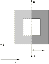
You define reflection symmetry to create a cavity that is composed of the user-defined
cavity surface plus its reflected image through a line or plane. You must identify the
dimensionality of the cavity when you define reflection symmetry.
Reflection of Two-Dimensional Cavities
You can define the cavity symmetry by reflecting the cavity surface through a line, as
shown in Figure 1.
Figure 1. Reflection symmetry through a line.
This type of reflection can be used only with two-dimensional cavities.
Interaction module: Create Interaction: Cavity radiation: Symmetry: Reflection: enter the z-axis symmetry value for the line of symmetry
Periodic Symmetry
You can define cavity symmetry by periodic repetition in a given direction. Physically,
periodic symmetry is understood as an infinite number of repetitions of the same image at
a periodic interval. Numerically, periodic symmetry has to be represented by a finite
number of repetitions of the periodic image. You can define the number of repetitions used
in the numerical calculation, n.
The periodic symmetry will result in a cavity composed of the user-defined cavity plus
twice n similar images, since the periodic symmetry is assumed
to apply in both the positive and negative directions. By default,
n=2.
Although symmetries do not increase the size of the view factor matrix, they do make its
calculation more expensive. Therefore, the number of repetitions should be minimized, but
the value of n should be large enough that the view factor
matrix is calculated accurately. Output variable
VFTOT can be used to check the amount of
closure implied by the symmetry. (See Controlling the Accuracy of View Factor Calculations below.)
Periodic symmetry for defining the cavity radiation view factor matrix does not impose
symmetry conditions automatically in the heat transfer analysis. It may be necessary to
impose appropriate constraints on the temperature and loading conditions at the nodes on
the periodic symmetry planes to obtain a meaningful solution from the underlying heat
transfer analysis.
You must identify the dimensionality of the cavity when you define periodic symmetry.
Periodic Symmetry of Two-Dimensional Cavities
You can create a cavity that is composed of a series of similar images generated by
repetition along a two-dimensional distance vector, as shown in Figure 4.
Figure 4. Two-dimensional periodic symmetry.
The repeated images are bounded by lines parallel to line
ab. The distance vector must be defined so that it points
away from line ab and into the domain of the model. This
type of periodic symmetry can be used only with two-dimensional cavities.
Interaction module: Create Interaction: Cavity radiation: Symmetry: Periodic: Number of periodic symmetries: n
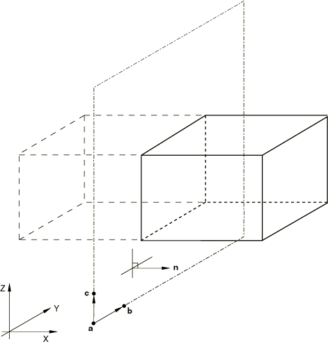
Periodic Symmetry of Three-Dimensional Cavities
You can create a cavity that is composed of a series of similar images generated by
repetition along a three-dimensional distance vector, as shown in Figure 5. The repeated images are bounded by planes that are parallel to plane
abc. The distance vector must be defined so that it
points away from plane abc and into the domain of the
model. This type of periodic symmetry can be used only with three-dimensional cavities.
Interaction module: Create Interaction: Cavity radiation: Symmetry: Periodic: Number of periodic symmetries: n
Periodic Symmetry of Axisymmetric Cavities
You can create a cavity that is composed of a series of similar images generated by
repetition in the z-direction, as shown in Figure 6.
Figure 6. Axisymmetric periodic symmetry.
The repeated images are bounded by lines of constant z-coordinate.
The z-distance vector must be defined so that it points away from
the z-constant periodic symmetry reference line and into the domain
of the model. This type of periodic symmetry can be used only with axisymmetric
cavities.
Interaction module: Create Interaction: Cavity radiation: Symmetry: Periodic: Number of periodic symmetries: n
Cyclic Symmetry
You can define cavity symmetry by cyclic repetition of the user-defined cavity surface
about a point or an axis. The cavity defined by cyclic repetition must cover 360°.
You must define the number of cyclically similar images that compose the cavity,
n. The angle of rotation about a point or axis used to create
cyclically similar images is equal to 360°/n.
You must identify the dimensionality of the cavity when you define cyclic symmetry.
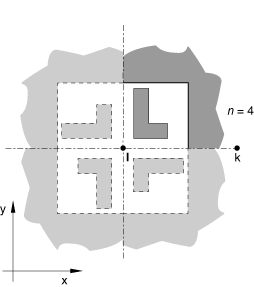
Cyclic Symmetry of Two-Dimensional Cavities
You can define the cavity symmetry by rotating the cavity about a point,
l, as shown in Figure 7.
Figure 7. Cyclic symmetry about a point.
The cavity surface defined in the model must be bounded by the line
lk and a line passing through
l at an angle, measured counterclockwise when looking
into the plane of the model, of 360°/n to
lk. This type of cyclic symmetry can be used only for
two-dimensional cavities.
Interaction module: Create Interaction: Cavity radiation:
Symmetry: Cyclic: toggle on Use cyclic symmetric,
Total number of sectors: n
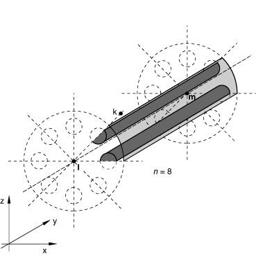
Cyclic Symmetry of Three-Dimensional Cavities
You can define the cavity symmetry by rotating the cavity about an axis,
lm, as shown in Figure 8. The cavity surface defined in the model must be bounded by the plane
lmk and a plane passing through the line
lm at an angle, measured clockwise when looking from
l to m, of
360°/n to lmk. Line
lk must be normal to line
lm. This type of cyclic symmetry can be used only for
three-dimensional cavities.
Interaction module: Create Interaction: Cavity radiation: Symmetry: Cyclic: toggle on Use cyclic symmetric,
Total number of sectors: n
Combining Symmetries
Reflection, periodic, and cyclic symmetries can be combined as shown in Table 1. Figure 9 through Figure 12 illustrate some possible symmetry combinations.
Table 1. Permissible number of symmetry definitions used in combination.
Reflection
Periodic
Cyclic
2D
3D
Axi
Restrictions
1
0
0
•
•
•
2
0
0
•
•
3
0
0
•
0
1
0
•
•
•
0
2
0
•
•
0
3
0
•
1
1
0
•
•
1
2
0
•
2
1
0
•
0
0
1
•
•
1
0
1
•
0
1
1
•
, , , are normals to lines or planes of reflection symmetry.
, , are distance vectors used to define periodic symmetry.
is the direction of the axis of cyclic symmetry in three-dimensional
cases.
Figure 9. Combination of two reflection symmetries in two dimensions. Figure 10. Combination of two periodic symmetries in two dimensions. Figure 11. Combination of one reflection symmetry and one periodic symmetry in two
dimensions. Figure 12. Combination of one cyclic symmetry and one periodic symmetry in three
dimensions.
Prescribing Motion during a Cavity Radiation Analysis
In many cavity radiation problems such as simulations of manufacturing sequences, radiation
view factors change because surfaces are moved during the analysis. You can specify surface
motions during heat transfer or coupled thermal-electrical analysis.
The prescribed motions affect only the calculation of view factors (and, therefore,
radiation fluxes) in heat transfer due to cavity radiation. They do not affect heat
conduction, storage, or distributed flux contributions.
You can define both the translational and rotational components of the motion within a step
independently. For example, you can prescribe the translational motion of a node set
according to a certain amplitude function and then prescribe the rotational motion of the
node set according to a different amplitude function. In each step, each component of motion
can be specified only once for any particular node.
Motions can also be prescribed during steps in which the cavity radiation is turned off, as
described below.
Translational Motion
Translations, , are specified in terms of global x-,
y-, and z-components unless a local coordinate
system is defined at the nodes for which motion is specified; then translations are
specified in terms of local x-, y-, and
z-components (see Transformed Coordinate Systems).
Translational displacements are always specified as total values of translational motion.
This treatment of translations is consistent with that used for displacement boundary
conditions (Boundary Conditions) in
stress/displacement analyses. The default is to apply translational motion.
Translational velocities can also be specified. Translational velocities always refer to
the current step; therefore, the rate of translational motion specified as a velocity is
in effect only during the step for which it is defined. This behavior is different from
velocity boundary conditions, where velocities stay in effect in subsequent steps if they
are not redefined.
Input File Usage
Use either of the following options to prescribe translational motion:
Surface motion is not supported with cavity radiation in Abaqus/CAE.
Rotational Motion
Displacements due to a rigid body rotation, , can be defined by specifying the magnitude of the rotation and the
rotation axis. In three dimensions the rotation axis is defined by specifying two points, and , on the axis of rotation. In two dimensions the rotation axis is assumed
to be normal to the plane of the model and is defined by specifying one point, .
The coordinates of the points defining the axis of rotation must be defined in the
configuration at the beginning of the step for which rigid body rotation is being defined.
Motion due to rigid body rotation during a step is specified as the amount of rotation
that takes place during that step only. Therefore, the rigid body rotation specified
during a step is local to that step; if no rigid body rotation is specified in the
following step, no further rotation occurs.
The treatment of rigid body rotations is different from that of translations: rigid body
rotations are specified incrementally from step to step while translations are specified
as total values.
Input File Usage
Use either of the following options to prescribe rotational motion:
Surface motion is not supported with cavity radiation in Abaqus/CAE.
Prescribing Large Rotational Motions
Prescribed rotational motions of more than radians or complex sequences of rotations about different directions
in three-dimensional models are most simply defined by specifying rotational velocities,
which allows the definition to be given in terms of the angular velocity instead of the
total rotation. Abaqus/Standard calculates the increment of rotation as the average of the angular velocities at the
beginning and end of each increment multiplied by the time increment. (See Conventions.)
Example
For example, if a rotation of about the z-axis is required, with no rotation
about the x- and y-axes, and assuming a step
time of 1.0, specify a constant angular velocity of as follows:
The angular velocity will be constant since the default variation for motions
prescribed using a predefined velocity field in a heat transfer or coupled
thermal-electrical step (both steady-state and transient) is a step function (see Defining an Analysis). An
amplitude reference could be used to specify other variations of the angular velocity.
If, in the next step, the same node (or node set) should have an additional rotation of radians about the global x-axis, assuming again a
step time of 1.0, prescribe a constant angular velocity as follows:
Motions involving two or more simultaneous rigid body rotations about different axes
cannot be specified directly. An example of simultaneous rigid body rotations is a
satellite rotating about its own axis while orbiting the earth. Such complex motions can
be defined with user subroutine UMOTION. This subroutine allows
specification of the time variation of the magnitude of the translational components of
the motion (degrees of freedom 1–3) at each node.
If you specify the magnitude of the translation as part of the prescribed motion
definition, it will be modified by the amplitude curve (if any) and passed into
subroutine UMOTION, where it can be
redefined.
When user subroutine UMOTION is used to define the
motion of a certain node set in a step, only one prescribed motion can be defined in
that step for that node set. The complete motion of all nodes in the node set during the
step must be defined in the user subroutine.
Surface motion is not supported with cavity radiation in Abaqus/CAE.
Simultaneous Translational and Rotational Motion
Whenever simultaneous translational and rotational motion is specified, the total motion
of a node during step k is defined as
where is the current location of the node due to the specified motion history, is the original location of the node, is the displacement of the node due to the translational motion
specified in the step, and is the displacement of the node due to rigid body rotation during step
i.
In these cases the translation is applied first and the rotation is then assumed to be
about the translated (material) axis. In other words, the displacement due to rigid body rotation during step i is
computed as the rotation about an axis defined by points and where
In the preceding equations and are the locations of the points used to define the axis of rotation for
the prescribed rotational motion (they refer to the configuration at the beginning of step
i) and is the displacement due to translational motion during the step (, where is the time at the end of step ).
Example
As an example, consider a three-dimensional problem with
x–y planar motion as shown in Figure 13.
Figure 13. Planar motion example.
The centroid of the object of interest is initially located at . In the first step the object is translated 4 length units in the
x-direction while at the same time it rotates clockwise 180° ( radians) about the z-axis at constant angular
velocity. This motion moves the object from position A to position
C in Figure 13. Halfway through this motion, at position B, the displacements
due to the rigid body rotation are calculated by applying the translation to the
z-axis (the axis of rotation) and then applying a 90° rotation
about this translated axis.
In the second step the object is translated −3 length units in the
y-direction only. This motion places the object at position
D with no additional rotation. Finally, in the third step the
object is simultaneously translated 5 length units at an angle of 53.13° to the
y-direction and rotated clockwise, again at constant angular
velocity, through 180° about the z-axis. This motion returns the
object to its original position.
Assuming that each step time is 1.0, the input required for the above motion sequence
is as follows:
Surface motion is not supported with cavity radiation in Abaqus/CAE.
Controlling the Frequency of View Factor Recalculation due to Motion
You can control how view factors are recalculated during a step as a result of prescribed
motion by specifying a value for the maximum allowable motion,
max, for a particular node set. View factor recalculation is
triggered if a displacement component at any node in the specified node set exceeds the
specified value for max.
You must respecify the value of max and the node set in every
step where recalculation is required; the values do not remain in effect for subsequent
steps.
View factor recalculation can be expensive; use discretion when choosing a value for
max.
The max and nset values must
always be specified together.
Abaqus/CAE Usage
View factor recalculation due to motion is not supported with cavity radiation in
Abaqus/CAE.
Controlling View Factor Calculation during the Analysis
The cavity radiation capability can be used in applications such as the simulation of
manufacturing sequences where radiation view factors change during the simulation.
Therefore, radiation view factor definitions provide significant flexibility for the control
of view factor calculations during a step.
Multiple radiation view factor definitions can be specified within a step definition if
different types of radiation and view factor calculations are required for different
cavities. Different types of view factor calculations can be specified for the same cavity
in different steps of the analysis.
By default, view factors are calculated at the beginning of the first step that includes a
radiation view factor definition. View factors are recalculated at the beginning of a
subsequent step only if the view factor definition changes in that step; for example, if
different surface blocking checks are specified for the same cavity. In a restart analysis
Abaqus/Standard reads the radiation view factors from the user-specified restart step and increment and
recalculates the view factors only if the view factor definitions have changed.
You can specify the name of the cavity for which radiation view factor control is being
specified. If you do not specify a cavity name, the radiation view factor definition applies
to all cavities in the model.
Radiation view factors are defined separately for each cavity radiation interaction
and apply to all steps in which that interaction is active.
Activating and Deactivating Cavity Radiation
There are practical situations in which it may be useful to switch cavity radiation
effects on and off during the analysis. For example, radiation may be taking place in a
cavity that is then filled with a fluid so that radiation is no longer significant; later
in the analysis, radiation may resume when the fluid is drained from the cavity. In such
cases you can use a radiation view factor definition to switch the radiation on and off in
any particular cavity during one or more steps of the analysis.
When cavity radiation is switched back on after having been switched off, Abaqus/Standard will use the last view factors calculated in the last step in which cavity radiation
was active. However, if motion is prescribed during the time that the cavity radiation is
switched off and one of the displacement components of a node in the specified node set
exceeds the value for the maximum allowable motion, max,
specified in the step during which cavity radiation is switched off, the view factors will
be recalculated at the beginning of the step in which the cavity radiation is switched
back on.
Input File Usage
Use the following option to turn view factor calculation off for a step:
Radiation view factors cannot be turned off or on for a selected step. You can use
the following options to turn a cavity radiation interaction off or on:
Interaction module: Interaction Manager: select a step and a cavity radiation interaction, Activate or Deactivate
Controlling the Accuracy of View Factor Calculations
Abaqus/Standard uses a progressive integration scheme for view factor calculation. When facets are
sufficiently far from each other, a lumped area approximation is used. If the facets are
close to each other but one of the facets is much larger than the other, an
infinitesimal-to-finite approximation is used. For all other cases a contour integral is
numerically calculated to compute the view factor. See View factor calculation for details.
Two nondimensional parameters are calculated for each facet pair to determine which
integration scheme is used:
where is the area of the smaller facet, is the area of the larger facet, and d is the
distance between their centroids. The lumped area approximation is used whenever the
nondimensional distance square parameter , where has a default value of 5.0. If , an infinitesimal-to-finite area approximation is used if the facet area
ratio , where has a default value of 64.0. Otherwise, a more precise calculation is
performed, involving the numerical integration of a contour integral.
You can customize the accuracy and speed of the view factor calculation by specifying the
parameters and and the number of integration points per edge. For example, Abaqus/Standard will used lumped area approximations throughout the whole model if is set to zero. Likewise, the more precise, albeit more expensive,
numerical integration method will always be used if and are set to very large numbers.
Input File Usage
RADIATION VIEW FACTOR, LUMPED AREA=P1, INFINITESIMAL=P2, INTEGRATION=integration points per edge
Abaqus/CAE Usage
Interaction module: Create Interaction: Cavity radiation: View factors: enter new values or accept the defaults for Infinitesimal facet area ratio, Gauss integration points per edge, and Lumped area distance-square value
View Factor Calculation Checks for Closed Cavities
You can provide a tolerance on the accuracy of the view factor calculation. In a closed
cavity the sum of the view factors for each cavity facet should be one. Abaqus/Standard compares the value of the specified tolerance to the largest view factor matrix row
sum deviation from unity; that is, . If the tolerance is violated for a closed cavity, the analysis is
terminated. The default view factor tolerance is 0.05. Failure to meet this criterion
may indicate a need for mesh refinement.
View Factor Calculations in Cavities with Symmetries
The view factor calculations account for the closure of a cavity implied by any cavity
symmetries. For cavities without periodic or cyclic symmetries the view factors are
calculated exactly for two-dimensional geometries, but approximations are made for
axisymmetric and three-dimensional geometries. These approximations become less accurate
as the distance between surfaces decreases. Define heat radiation to model closely
spaced surfaces (see Thermal Contact Properties).
View Factor Calculations in Open Cavities
If the sum of the view factors for any facet in an open cavity (defined by specifying a
value for the ambient temperature) deviates from unity by more than the specified view
factor tolerance, radiation to the ambience will take place from all facets. In nearly
closed cavities this deviation may be small. If the tolerance is not violated, radiation
to the external medium is not included even though the cavity is defined to be open; a
warning message is issued to this effect. You can reduce the view factor tolerance to
include such radiation.
Controlling Checks for Surface Blocking
Heat is transferred between surfaces that have unobstructed direct views of each other
(see Figure 14); “blocking” may occur in geometrically complex cavities.
Figure 14. Illustrations of blocking.
Surface blocking checks may be computationally expensive in cavities with many surfaces;
therefore, significant computational time may be saved by specifying which surfaces are
potential blocking surfaces, as described below.
View factor calculations with blocking surfaces are especially sensitive to mesh
refinement. If a mesh is too coarse, the view factors may not add up to one (in a closed
cavity). To obtain accurate results, the mesh should be refined until the view factors can
be summed accurately.
Full Blocking Checks
By default, Abaqus/Standard will check for blocking of every surface with itself and all other surfaces.
Reducing Computations for Surfaces That Are Far Apart
In cases where there are many surfaces in the cavity, surfaces separated by more than a
certain distance may not be able to “see” each other for the purposes of radiation because
of blocking by other surfaces. You can specify the distance beyond which view factors need
not be calculated, which reduces the computational effort required for the view factor
calculations.
The cavity radiation heat transfer between facets of a surface in Abaqus is modeled using a full, unsymmetric matrix defining interactions between each node and
all others in the cavity. For surfaces with large numbers of nodes this matrix may be
large, resulting in memory requirements that are significantly larger than those for the
finite element portion of the analysis without the cavity radiation interaction.
To minimize memory requirements and computational cost for cavity radiation heat transfer
analysis, the cavity can be defined using a coarser mesh of heat transfer shell elements
having a single degree of freedom per node. The overlaid element should have minimal heat
capacity and conduction, and it should be used for the definition of the cavity in place
of the physical, multiple-degree-of-freedom shell. The overlaid element should be used to
define the main surface in a tied coupling constraint (Mesh Tie Constraints); the
multiple-degree-of-freedom, physical, heat transfer shell element forms the secondary
surface.
Initial Conditions
By default, the initial temperature of all nodes is zero. You can specify nonzero initial
temperatures in a cavity radiation analysis; see Defining Initial Temperatures.
In a heat transfer analysis involving forced convection through the mesh, you can define
nonzero initial mass flow rates at the nodes of the forced convection/diffusion heat
transfer elements in the model (see Uncoupled Heat Transfer Analysis).
Boundary Conditions
You can specify boundary conditions to prescribe temperatures (degree of freedom 11) at the
nodes (see Boundary Conditions). Shell elements
have additional temperature degrees of freedom 12, 13, etc. through the thickness (see Conventions). Boundary
conditions can be specified as functions of time by referring to amplitude curves (Amplitude Curves).
For purely diffusive elements, a boundary without any prescribed boundary conditions
(natural boundary condition) corresponds to an insulated surface. For forced
convection/diffusion elements, only the flux associated with conduction is zero; energy is
free to convect across an unloaded surface. This natural boundary condition correctly models
areas where fluid is crossing a surface (as, for example, at the upstream and downstream
boundaries of the mesh) and prevents spurious reflections of energy back into the mesh.
Loads
The following types of loading can be prescribed in addition to the cavity radiation, as
described in Thermal Loads:
Concentrated heat fluxes
Body fluxes and distributed surface fluxes
Convective film conditions and radiation conditions
Predefined Fields
You cannot specify temperatures as field variables in heat transfer or coupled
thermal-electrical analyses. Boundary conditions should be used instead, as described above.
You can specify values of other user-defined field variables during the analysis. These
values will affect field-variable-dependent material properties, if any. See Predefined Fields.
In addition to the elements that you define, Abaqus/Standard uses internal elements that are generated automatically from your definition of radiation
cavities.
Output
The following output variables are available for cavity radiation:
Surface variables
RADFL
Radiation flux per unit area. This variable does include heat flux to ambient in an
open cavity.
RADFLA
Radiation flux over a facet.
RADTL
Time integrated radiation per unit area.
RADTLA
Time integrated radiation over a facet.
VFTOT
Total view factor for a facet (sum of the view factor values in the row of the view
factor matrix corresponding to the facet).
FTEMP
Facet temperature.
All of the output variables are listed in Abaqus/Standard Output Variable Identifiers. Abaqus/CAE supports motion display and can display surface- and element-based results.
Writing the View Factor Matrices to the Results File
You can write the view factor matrices for cavity radiation interactions in heat transfer
or coupled thermal-electrical analyses to the results (.fil) file if
parallel decomposition for the cavity is not enabled.. The entire radiation view factor
matrix is written for each cavity radiation element in the specified cavity.
You can control the frequency of view factor matrix output by specifying the required
output frequency in increments. The default output frequency is 1. Specify an output
frequency of 0 to suppress output. The output will always be written at the last increment
of each step unless you specify an output frequency of 0.
View factor output is not supported in Abaqus/CAE.
Requesting Surface Variable Output
For the cavity radiation interaction, you can request cavity-, element-, or surface-based
radiation output such as radiation fluxes, view factor totals for a facet, and facet
temperatures to the data, results, and/or output database files. The output requests can
be repeated as often as necessary to request output for different variables, different
cavities, different surfaces, different element sets, etc. The surface variables that can
be requested are listed above.
You can specify the particular cavity, element set, or surface for which output is being
requested. If you do not specify a cavity, element set, or surface, output will be
provided for all cavities in the model. The same cavity, element set, or surface can
appear in several radiation output requests.
By default, no cavity radiation data output will be provided. If you define a radiation
output request without specifying the desired output variables, all six cavity radiation
surface variables will be output.
You can control the frequency of radiation output by specifying the required output
frequency in increments. The default output frequency is 1. Specify an output frequency of
0 to suppress output. The output will always be written at the last increment of each step
unless you specify an output frequency of 0.
Input File Usage
Use one of the following options to obtain output in the data file:
Cavity radiation output to the data file and the results file are not supported in
Abaqus/CAE.
Use the following options to obtain output in the output database:
Step module: history output request editor: Thermal: select the output variables
Printed Output
The output tables generated by a radiation output request to the data file are
organized on a surface-by-surface basis. The rows that will appear in a particular table
are defined by choosing a cavity, surface, or element set: each row of a table
corresponds to an individual element face that is part of the cavity, surface, or
element set chosen. If all of the variables in a row of a table are zero, the row is not
printed.
The first column of each table is the element number, and the second column is the
element face identifier. You choose the variables to appear in the remaining columns.
There is no limit to the number of tables that can be defined.
As an example, consider a heat transfer model containing a cavity named
CAV1, which, in turn, is composed of surfaces
SURF1 and SURF2. If
you request output of radiation flux
(RADFL) and facet temperature
(FTEMP) to the data file for this
model, two tables will appear in the data file. One table will contain
RADFL and
FTEMP output for all element faces
composing surface SURF1, and the other table will
contain the same output variables for all element faces making up surface
SURF2.
By default, Abaqus/Standard writes a summary of the maximum and minimum values in each column of the table. You
can choose to suppress this summary. In addition, you can choose to print the total of
each column in the table, which is useful, for example, to sum radiation fluxes over all
facets composing a radiation surface. By default, these totals are not printed.
Input File Usage
Use the following option to control output of the summary information to the data
file:
Cavity radiation output to the data file is not supported in Abaqus/CAE.
Input File Template
The following template shows the options required for a transient, cavity radiation
analysis of a closed two-dimensional symmetric cavity. All surfaces within the cavity
topcav have the same emissivity. The surface
surf2 moves (translation only) during the analysis. In
the second step surface surf2 stops moving, cavity
radiation is turned off, all thermal loads except the surface convection are removed, and a
steady-state heat transfer analysis is conducted to determine the final temperature of the
system.
HEADING
…
PHYSICAL CONSTANTS, ABSOLUTE ZERO=, STEFAN BOLTZMANN=
SURFACE, NAME=surf1, PROPERTY=surfp
elset1, S1
elset2, S2
SURFACE, NAME=surf2, PROPERTY=surfp
elset3,
SURFACE PROPERTY, NAME=surfp
EMISSIVITYData lines to define the emissivity of the surfaces in the modelCAVITY DEFINITION, NAME=topcav
surf1, surf2
INITIAL CONDITIONS, TYPE=TEMPERATUREData lines to prescribe initial temperatures at the nodesAMPLITUDE, NAME=motion
Data lines to define amplitude curve to be used for motion of surface surf2
AMPLITUDE, NAME=film
Data lines to define amplitude curve to be used for the convection film coefficient, h
*************
** Step 1
*************
STEPHEAT TRANSFER, MXDEM=, DELTMX=
Data line to define incrementationRADIATION VIEW FACTOR, CAVITY=topcav, VTOL=tol, SYMMETRY=outer,
NSET=nset, MDISP=maxRADIATION SYMMETRY, NAME=outer
REFLECTION, TYPE=LINEData line to define line of symmetryMOTION, TRANSLATION, TYPE=DISPLACEMENT, AMPLITUDE=motion
Data line to define motion of nodes on surface surf2
CFLUX and/or DFLUXData lines to define concentrated and/or distributed fluxesBOUNDARYData lines to prescribe temperatures at selected nodesFILM, FILM AMPLITUDE=film
Data lines to define surface convection
**
RADIATION PRINT, CAVITY=topcav, SUMMARY=YES, TOTALS=YESData lines requesting cavity radiation surface variable outputRADIATION FILE, CAVITY=topcav, FREQUENCY=4
Data lines requesting cavity radiation surface variable outputNODE PRINTData lines requesting nodal output such as temperaturesEL PRINTData lines requesting element output such as heat fluxEND STEP
*************
** Step 2
*************
STEPHEAT TRANSFER, STEADY STATEData line to define incrementationRADIATION VIEW FACTOR, OFFCFLUX, OP=NEWDFLUX, OP=NEWEND STEP