You can apply acoustic loads in transient and steady-state dynamic analysis
procedures to model boundary impedance, nonreflecting boundaries, concentrated
pressure-conjugate loads, and incident wave loading.
The following types of acoustic loads are available:
Boundary impedance defined on element faces or on surfaces.
Nonreflecting radiation boundaries in exterior problems such as a structure vibrating in
an acoustic medium of infinite extent.
Concentrated pressure-conjugate loads prescribed at acoustic element nodes.
Temporally and spatially varying pressure loading on acoustic and solid surfaces due to
incident waves traveling through the acoustic medium.
A boundary impedance specifies the relationship between the pressure of an acoustic medium
and the normal motion at the boundary. Such a condition is applied, for example, to include
the effect of small-amplitude “sloshing” in a gravity field or the effect of a compressible,
possibly dissipative, lining (such as a carpet) between an acoustic medium and a fixed,
rigid wall or structure.
The impedance boundary condition at any point along the acoustic medium surface is governed
by
where
is the acoustic particle velocity in the outward normal direction of the acoustic
medium surface,
p
is the acoustic pressure,
is the time rate of change of the acoustic pressure,
is the proportionality coefficient between the pressure and the displacement normal
to the surface, and
is the proportionality coefficient between the pressure and the velocity normal to
the surface.
This model can be conceptualized as a spring and dashpot in series placed between the
acoustic medium and a rigid wall. The spring and dashpot parameters are and , respectively, defined per unit area of the interface surface. These
reactive acoustic boundaries can have a significant effect on the pressure distribution in
the acoustic medium, in particular if the coefficients and are chosen such that the boundary is energy absorbing. If no impedance,
loads, or fluid-solid coupling are specified on the surface of an acoustic mesh, the
acceleration of that surface is assumed to be zero. This is equivalent to the presence of a
rigid wall at that boundary.
Use of the subspace-based steady-state dynamics procedure is not recommended if reactive
acoustic boundaries with strong absorption characteristics are used. Since the effect of is not taken into account in an eigenfrequency extraction step, the
eigenmodes might have shapes that are significantly different from the exact solution.
Sloshing of a Free Surface
To model small-amplitude “sloshing” of a free surface in a gravity field, set and , where is the density of the fluid and g is the
gravitational acceleration (assumed to be directed normal to the surface). This relation
holds for small volumetric drag.
Acoustic-Structural Interface
The impedance boundary condition can also be placed at an acoustic-structural interface.
In this case the boundary condition can be conceptualized as a spring and dashpot in
series placed between the acoustic medium and the structure. The expression for the
outward velocity still holds, with now being the relative outward velocity of the acoustic medium and the
structure:
where is the velocity of the structure, is the velocity of the acoustic medium at the boundary, and is the outward normal to the acoustic medium.
Steady-State Dynamics
In a steady-state dynamics analysis the expression for the outward velocity can be
written in complex form as
where is the circular frequency (radians/second) and we define
The term is the complex admittance of the boundary, and is its complex impedance. Thus, a required complex impedance or
admittance value can be entered for a given frequency by specifying the parameters and .
Specifying Impedance Conditions
You specify impedance coefficient data in an impedance property table. You can describe
an impedance table in terms of the admittance parameters, and , or in terms of the real and imaginary parts of the impedance. In the
latter case Abaqus converts the user-defined table of impedance data to the admittance parameter form for
the analysis.
The parameters in the table can be specified over a range of frequencies. The required
values are interpolated from the table in steady-state harmonic response analysis only;
for other analysis types, only the first table entry is used. The name of the impedance
property table is referred to from a surface-based or element-based impedance definition.
In Abaqus/CAE impedance conditions are always surface-based; surfaces can be defined as collections
of geometric faces and edges or collections of element faces and edges.
In a steady-state dynamics analysis you cannot specify impedance conditions on a surface
on which incident wave loading is applied.
Input File Usage
Use the following option to specify an impedance using a table of admittance
parameters (default):
Use the following input to specify an impedance using a table of admittance
parameters:
Interaction module: Create Interaction Property: Name: impedance property table name and Acoustic impedance: Data type: Admittance
Use the following input to specify an impedance using a table of the real and
imaginary parts of the impedance:
Interaction module: Create Interaction Property: Name: impedance property table name and Acoustic impedance: Data type: Impedance
Specifying Surface-Based Impedance Conditions
You can define the impedance condition on a surface. The impedance is applied to
element edges in two dimensions and to element faces in three dimensions. The
element-based surface (see Element-Based Surface Definition) contains
the element and face information.
Input File Usage
SIMPEDANCE, PROPERTY=impedance property table namesurface name
Alternatively, you can define the impedance condition on element faces. The impedance
is applied to element edges in two dimensions and to element faces in three dimensions.
The edge or face of the element on which the impedance is placed is identified by an
impedance load type and depends on the element type (see About the Element Library).
Input File Usage
IMPEDANCE, PROPERTY=impedance property table nameelement number or set name, impedance load type label
Abaqus/CAE Usage
Element-based impedance conditions are not supported in Abaqus/CAE. However, similar functionality is available using surface-based impedance
conditions.
Modifying or Removing Impedance Conditions
Impedance conditions can be added, modified, or removed as described in About Loads.
Radiation Boundaries for Exterior Problems
An exterior problem such as a structure vibrating in an acoustic medium of infinite extent
is often of interest. Such a problem can be modeled by using acoustic elements to model the
region between the structure and a simple geometric surface (located away from the
structure) and applying a radiating (nonreflecting) boundary condition at that surface. The
radiating boundary conditions are approximate, so the error in an exterior acoustic analysis
is controlled not only by the usual finite element discretization error but also by the
error in the approximate radiation condition. In Abaqus the radiation boundary conditions converge to the exact condition in the limit as they
become infinitely distant from the radiating structure. In practice, these radiation
conditions provide accurate results when the surface is at least one-half wavelength away
from the structure at the lowest frequency of interest.
Except in the case of a plane wave absorbing condition with zero volumetric drag, the
impedance parameters in Abaqus/Standard are frequency dependent. The frequency-dependent parameters are used in the
direct-solution and subspace-based steady-state dynamics procedures. In direct time
integration procedures the zero-drag values for the constants and are used. These values will give good results when the drag is small.
(Small volumetric drag here means where is the density of the acoustic medium and is the circular excitation frequency or sound wave frequency.)
A direct-solution steady-state dynamics procedure (Direct-Solution Steady-State Dynamic Analysis) must include
both real and complex terms if nonreflecting (also called quiet) boundaries are present,
because nonreflecting boundaries represent a form of damping in the system.
Several radiating boundary conditions are implemented as special cases of the impedance
boundary condition. The details of the formulation are given in Coupled acoustic-structural medium analysis.
Element-based impedance conditions are not supported in Abaqus/CAE. However, similar functionality is available using surface-based impedance conditions.
Planar Nonreflecting Boundary Condition
The simplest nonreflecting boundary condition available in Abaqus assumes that the plane waves are normally incident on the exterior surface. This planar
boundary condition ignores the curvature of the boundary and the possibility that waves in
the simulation might impinge on the boundary at an arbitrary angle. The planar
nonreflecting condition provides an approximation: acoustic waves are transmitted across
such a boundary with little reflection of energy back into the acoustic medium. The amount
of energy reflected is small if the boundary is far away from major acoustic disturbances
and is reasonably orthogonal to the direction of dominant wave propagation. Thus, if an
exterior (unbounded domain) problem is to be solved, the nonreflecting boundary should be
placed far enough away from the sound source so that the assumption of normally impinging
waves is sufficiently accurate. This condition would be used, for example, on the exhaust
end of a muffler.
Improved Nonreflecting Boundary Condition for Plane Waves
For the planar nonreflecting boundary condition to be accurate, the plane waves must be
normally incident to a planar boundary. However, the angle of incidence is generally
unknown in advance. A radiating boundary condition that is exact for plane waves with
arbitrary angles of incidence is available in Abaqus. The radiating boundary can have any arbitrary shape. This boundary impedance is
implemented only for transient dynamics.
Four other types of absorbing boundary conditions that take the geometry of the radiating
boundary into account are implemented in Abaqus: circular, spherical, elliptical, and prolate spheroidal. These boundary conditions
offer improved performance over the planar nonreflecting condition if the nonreflecting
surface has a simple, convex shape and is close to the acoustic sources. The various types
of absorbing boundaries are selected by defining the required geometric parameters for the
element-based or surface-based impedance definition.
The geometric parameters affect the nonreflecting surface impedance. To specify a
nonreflecting boundary that is circular in two dimensions or a right circular cylinder in
three dimensions, you must specify the radius of the circle. To specify a nonreflecting
spherical boundary condition, you must specify the radius of the sphere. To specify a
nonreflecting boundary that is elliptical in two dimensions or a right elliptical cylinder
in three dimensions or to specify a prolate spheroid boundary condition, you must specify
the shape, location, and orientation of the radiating surface. The two parameters
specifying the shape of the surface are the semimajor axis and the eccentricity. The
semimajor axis, a, of an ellipse or prolate spheroid is analogous to
the radius of a sphere: it is one-half the length of the longest line segment connecting
two points on the surface. The semiminor axis, b, is one-half the
length of the longest line segment that connects two points on the surface and is
orthogonal to the semimajor axis line. The eccentricity, , is defined as .
Combining Different Radiation Conditions in the Same Problem
Since the radiation boundary conditions for the different shapes are spatially local
and do not involve discretization in the infinite exterior domain, an exterior boundary
can consist of the combination of several shapes. The appropriate boundary condition can
then be applied to each part of the boundary. For example, a circular cylinder can be
terminated with hemispheres (see Fully and sequentially coupled acoustic-structural analysis of a muffler), or an
elliptical cylinder can be terminated with prolate spheroidal halves. This modeling
technique is most effective if the boundaries between surfaces are continuous in slope
as well as displacement, although this is not essential.
Concentrated Pressure-Conjugate Load
Distributed “loads” on acoustic elements can be interpreted as normal pressure gradients
per unit density (dimensions of force per unit mass or acceleration). When used in Abaqus, the applied distributed loads must be integrated over a surface area, yielding a
quantity with dimensions of force times area per unit mass (or volumetric acceleration). For
analyses in the frequency domain and for transient dynamic analyses where the volumetric
drag is zero, this acoustic load is equal to the volumetric acceleration of the fluid on the
boundary. For example, a horizontal, flat rigid plate oscillating vertically imposes an
acceleration on the acoustic fluid and an acoustic “load” equal to this acceleration times
the surface area of the plate. For the transient dynamics formulation in the presence of
volumetric drag, however, the specified “load” is slightly different. It is also a force
times area per unit mass; but this force effect is partially lost to the volumetric drag, so
the resulting volumetric acceleration of the fluid on the boundary is reduced. Noting this
distinction for the special case of volumetric drag and transient dynamics, it is
nevertheless convenient to refer to acoustic “loads” as volumetric accelerations in general.
An inward volumetric acceleration can be applied by a positive concentrated load on degree
of freedom 8 at a node of an acoustic element that is on the boundary of the acoustic
medium. In Abaqus/Standard you can specify the in-phase (real) part of a load (default) and the out-of-phase
(imaginary) part of a load. Inward particle accelerations (force per unit mass in transient
dynamics) on the face of an acoustic element should be lumped to concentrated loads
representing inward volumetric accelerations on the nodes of the face in the same way that
pressure on a face is lumped to nodal forces on stress/displacement elements.
Input File Usage
Use the following option to define the real part of the load:
Load module: Create Load: choose Acoustic for the Category and Inward volume acceleration for the Types for Selected Step
Incident Wave Loading due to External Sources
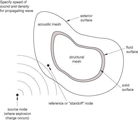
Abaqus provides a type of distributed load for loads due to external wave sources. Individual
spherical monopole or individual or diffuse planar sources can be defined, subjecting the
fluid and solid region of interest to an incident field of waves. Waves produced by an
explosion or sound source propagate from the source, impinging on and passing over the
structure, producing a temporally and spatially varying load on the structural surface. In
the fluid the pressure field is affected by reflections and emissions from the structure as
well as by the incident field from the source itself. The incident wave loads on acoustic
and/or solid meshes depend on the location of the source node, the properties of the
propagating fluid, and the reference time history or frequency dependence specified at the
reference (“standoff”) node as indicated in Figure 1.
Figure 1. Incident wave loading model.
Several distinct modeling methods can be used in Abaqus with incident wave loading, requiring different approaches to applying the incident wave
loads. For problems involving solid and structural elements only (for example, where the
incident wave field is due to waves in air) the wave loading is applied roughly like a
distributed surface load. This might apply to an analysis of blast loads in air on a vehicle
or building (see Example: Airblast Loading on a Structure, shown in Figure 6). In Abaqus/Explicit the CONWEP model can be used for air blast loading on
solid and structural elements, without the need to model the fluid medium. Deformation of a sandwich plate under CONWEP blast loading is an example of
a blast loading problem.
Incident wave loads (with the exception of CONWEP loading)
can be applied to beam structures as well; this is a common modeling method for ship
whipping analysis and for steel frame buildings subject to blast loads. Incident wave loads
can be applied to surfaces defined on two- or three-dimensional beam elements. However,
incident wave loads can be applied only to three-dimensional beams for transient dynamic
analysis where beam fluid inertia is defined. Incident wave loads cannot be defined on frame
elements, line spring elements, three-dimensional open-section beam elements, or
three-dimensional Euler-Bernoulli beams.
In underwater explosion analyses (for example, a ship or submerged vehicle subjected to an
underwater explosion loading as depicted in Figure 4 and Figure 5) the fluid is also discretized using a finite element model to capture the effects of the
fluid stiffness and inertia. For these problems involving both solid and acoustic elements,
two formulations of the acoustic pressure field exist. First, the acoustic elements can be
used to model the total pressure in the medium, including the effects of the incident field
and the overall system's response. Alternatively, the acoustic elements can be used to model
only the response of the medium to the wave loads, not the wave pulse itself. The former
case will be referred to as the “total wave” formulation, the latter as the “scattered wave”
formulation.
Incident wave interactions are also used to model sound fields impinging on structures or
acoustic domains. The acoustic field scattered by a structure or the sound transmitted
through the structure might be of interest. Usually, sound scattering and transmission
problems are modeled using the scattered formulation with steady-state dynamic procedures.
Transient procedures can also be used, in a manner analogous to underwater explosion
analysis problems.
Scattered and Total Wave Formulations
The distinction between the total wave formulation and the scattered wave formulation is
relevant only when incident wave loads are applied. The total wave formulation is more
closely analogous to structural loading than the scattered wave formulation: the boundary
of the acoustic medium is specified as a loaded surface, and a time-varying load is
applied there, which generates a response in the acoustic medium. This response is equal
to the total acoustic pressure in the medium. The scattered wave formulation exploits the
fact that when the acoustic medium is linear, the response in the medium can be decomposed
into a sum of the incident wave and the scattered field. The total wave formulation must
be used when the acoustic medium is nonlinear due to possible fluid cavitation (see Loading due to an incident dilatational wave field).
Table 1 describes the procedure types for which each formulation is supported.
Table 1. Supported procedures for scattered and total wave formulations.
Procedure
Scattered
Total Wave
Steady-state dynamics
Yes
No
Transient
Yes
Yes
Scattered Wave Formulation
When the mechanics of a fluid can be described as linear, the observed total acoustic
pressure can be decomposed into two components: the known incident wave and the
“scattered” wave that is produced by the interaction of the incident wave with
structures and/or fluid boundaries. When this superposition is applicable, it is common
practice to seek the “scattered” wave field solution directly. When using the scattered
wave formulation, the pressures at the acoustic nodes are defined to be only the
scattered part of the total pressure. Both acoustic and solid surfaces at the
acoustic-structural interface should be loaded in this case.
When using incident wave loads in steady-state dynamic procedures, the scattered wave
formulation must be used.
Input File Usage
Use the following option to specify the scattered wave formulation
(default):
Any module: ModelEdit Attributesmodel_name. Toggle on Specify acoustic wave formulation: select Scattered wave
Total Wave Formulation
The total wave formulation (see Coupled acoustic-structural medium analysis) is
particularly applicable when the acoustic medium is capable of cavitation, rendering the
fluid mechanical behavior nonlinear. It should also be used if the problem contains
either a curved or a finite extent boundary where the pressure history is prescribed.
Only the outer acoustic surfaces should be loaded with the incident wave in this case,
and the incident wave source must be located exterior to the fluid model. Any impedance
or nonreflecting condition that might exist on this outer acoustic boundary applies only
on the part of the acoustic solution that does not include the prescribed incident wave
field (that is, only the scattered field is subject to the nonreflecting condition).
Thus, the applied incident wave loading will travel into the problem domain without
being affected by the nonreflecting conditions on the outer acoustic surface.
In the total wave formulation the acoustic pressure degree of freedom stands for the
total dynamic acoustic pressure, including contributions from incident and scattered
waves and, in Abaqus/Explicit, the dynamic effects of fluid cavitation. The pressure degree of freedom does not
include the acoustic static pressure, which can be specified as an initial condition
(see Defining Initial Acoustic Static Pressure). This acoustic static pressure is used only in determining the cavitation status of
the acoustic element nodes and does not apply any static loads to the acoustic or
structural mesh at their common wetted interface. It does not apply to analyses using
Abaqus/Standard.
Input File Usage
Use the following option to specify the total wave formulation:
Any module: ModelEdit Attributesmodel_name. Toggle on Specify acoustic wave formulation: select Total wave
Initialization of Acoustic Fields
For transient dynamics, when the total wave formulation is used with the incident wave
standoff point located inside the acoustic finite element domain, the acoustic solution is
initialized to the values of the incoming incident wave. This initialization is performed
automatically, for pressure-based incident wave amplitude definitions only, at the
beginning of the first direct-integration dynamic step in an analysis; in restarted
analyses, steps are counted from the beginning of the initial analysis. This
initialization not only saves computational time but also applies the incident wave
loading without significant numerical dissipation or distortion. During the initialization
phase all incident wave loading definitions in the first dynamic analysis step are
considered, and all acoustic element nodes are initialized to the incident wave field at
time zero. Incident wave loads specified with different source locations count as separate
load definitions for the purpose of initialization of the acoustic nodes. Any reflections
of the incident wave loads are also taken into account during the initialization phase.
Describing Incident Wave Loading
To use incident wave loading, you must define the following:
information that establishes the direction and other properties of the incident wave,
the time history or frequency dependence of the source pulse at some reference
(“standoff”) point,
the fluid and/or solid surfaces to be loaded, and
any reflection plane outside the problem domain, such as a seabed in an underwater
explosion study, that would reflect the incident wave onto the problem domain.
Two interfaces are available in Abaqus for applying incident wave loads: a preferred interface that is
supported in Abaqus/CAE and an alternative interface that has been available in previous releases and is not supported in Abaqus/CAE. The preferred interface is conceptually the same as the alternative interface
and uses essentially the same data. The preferred interface options include the term
“interaction” to distinguish them from the incident wave and incident wave property
options of the alternative interface. Unless otherwise specified, the discussion in this
section applies to both of the interfaces. The usages for the preferred interface are
included in the discussion; the usages for the alternative interface are described in
Alternative Incident Wave Loading Interface below. Refer
to the example problems discussed at the end of this section to see how the incident wave
loading is specified using the preferred interface.
Prescribing Geometric Properties and the Speed of the Incident Wave
You must refer to a property definition for each prescribed incident wave. Incident
wave loads in Abaqus might be either planar, spherical, or diffuse. You select a planar incident wave
(default), spherical incident wave, or a diffuse field in the incident wave property
definition.
Planar incident waves maintain constant amplitude as they travel in space;
consequently, the speed and direction of travel are the critical parameters to define.
The speed is defined in the incident wave interaction property definition, and the
direction is determined by the locations of the source and standoff points you define as
part of the incident wave interaction.
For spherical incident wave definitions, the wave reduces in amplitude as a function of
the distance from the source. By default, the amplitude of a spherical wave is inversely
proportional to the distance from the source; this behavior is called “acoustic”
propagation. For the preferred interface you can modify the default propagation behavior
to define spatial decay of the incident wave field. The dimensionless constants , , and are used to define the spatial decay as a function of the distance between the source point and the loaded point and the distance between the source point and the standoff point:
In Abaqus incident wave interactions can be used to simulate diffuse incident fields. Diffuse
fields are characteristic of reverberant spaces or other situations in which waves from
many directions strike a surface. For example, reverberant chambers are constructed
intentionally in acoustic test facilities for sound transmission loss measurements. The
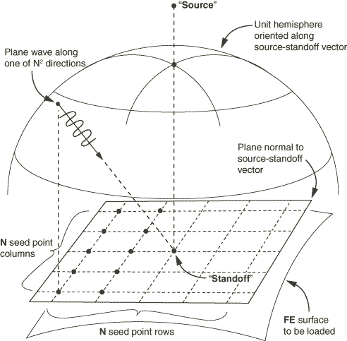
diffuse field model used in Abaqus, as shown in Figure 2, allows you to specify a seed number ; deterministic incident plane waves travel along vectors distributed
over a hemisphere so that the incident power per solid angle approximates a diffuse
incident field.
Figure 2. Diffuse loading model.
The fluid and the solid surfaces where the incident loading acts are specified in the
incident wave loading definition. The incoming wave load is further described by the
locations of its source point and of a reference (“standoff”) point where the wave
amplitude is specified. For information on how to specify these surfaces and the
standoff point, see Identifying the Fluid and the Solid Surfaces for Incident Wave Loading and The Standoff Point below. For a planar wave the specified locations of the source and the standoff
points are used to define the direction of wave propagation.
The speed of the incident wave is prescribed by giving the properties for the incident
wave-bearing acoustic medium. These specified properties should be consistent with the
properties specified for the fluid discretized using acoustic elements.
For the preferred interface you must define nodes corresponding to the source and
standoff points for the incident wave; the node numbers or set names must be specified
for each incident wave definition. The node set names, if used, must contain only a
single node. Neither the source node nor the standoff node should be connected to any
elements in the model.
Input File Usage
INCIDENT WAVE INTERACTION PROPERTY,
NAME=wave property name, TYPE=PLANE or SPHEREspeed of sound, fluid mass density, A, B, CINCIDENT WAVE INTERACTION, PROPERTY=wave property namefluid surface name, source node, standoff node, reference magnitude
The constants A, B, and
C apply only for spherical incident waves with
generalized spatial decay propagation.
The seed number N generates planar incident waves with
directions distributed on a hemisphere centered at the standoff point.
Abaqus/CAE Usage
Interaction module: Create Interaction Property: Name: wave property name and Incident wave, Speed of sound in fluid: speed of sound, Fluid density: fluid mass density
Select one of the following definitions:
Definition: PlanarDefinition: Spherical, Propagation model: AcousticDefinition: Spherical, Propagation model: Generalized decay,
enter values for A, B, and CDefinition: Diffuse, Seed number: NCreate Interaction: Incident wave: select the source point, select the standoff point, select the region: Wave property: wave property name, Reference magnitude: reference magnitude
Identifying the Fluid and the Solid Surfaces for Incident Wave Loading
In the scattered wave formulation the incident wave loading must be specified on all
fluid and solid surfaces that reflect the incident wave with two exceptions:
those fluid surfaces that have the pressure values directly prescribed using
boundary conditions; and
those fluid surfaces that have symmetry conditions (the symmetry must hold for both
the loading and the geometry).
In problems with a fluid-solid interface both surfaces must be specified in the
incident wave loading definition for the scattered formulation. See Example: Submarine Close to the Free Surface, shown
in Figure 4.
When the total pressure-based formulation is specified, the incident wave loading must
be specified only on the fluid surfaces that border the infinite region that is excluded
from the model. Typically, these surfaces have a nonreflecting radiation condition
specified on them, and the implementation ensures that the radiation condition is
enforced only on the scattered response of the modeled domain and not on the incident
wave itself. See Example: Submarine Close to the Free Surface and
Example: Surface Ship,
shown in Figure 4 and Figure 5, respectively.
In certain problems, such as blast loads in air, you might decide that the blast wave
loads on a structure need to be modeled, but the surrounding fluid medium itself does
not. In these problems the incident wave loading is specified only on the solid surfaces
since the fluid medium is not modeled. The distinction between the scattered wave
formulation and the total wave formulation for handling the incident wave loading is not
relevant in these problems since the wave propagation in the fluid medium is of no
interest.
The Standoff Point
In transient analyses the standoff point is a reference point used to specify the pulse
loading time history: it is the point at which the user-defined pulse history is assumed
to apply with no time delay, phase shift, or spreading loss. In steady-state analyses
using discrete planar or spherical sources, the standoff point is the point at which the
incident field has zero phase.
In transient analyses the standoff point should be defined so that it is closer to the
source than any point on the surfaces in the model that would reflect the incident wave.
Doing so ensures that all the points on these surfaces will be loaded with the specified
time history of the source and that the analysis begins before the wave overtakes any
portion of these surfaces. To save analysis time, the standoff point is typically on or
near the solid surface where the incoming incident wave would be first deflected (see
Example: Submarine Close to the Free Surface,
shown in Figure 4). However, the standoff point is a fixed point in the analysis: if the loaded
surfaces move before the incident wave loading begins, due to previous analysis steps or
geometric adjustments, the surfaces might envelop the specified standoff point. Care
should be taken to define a standoff point such that it remains closer to the incident
wave source point than any point on the loaded surfaces at the onset of the loading.
When the total wave formulation is used and the incident wave loading is specified in
the first step of the analysis in terms of pressure history, Abaqus automatically initializes the pressure and the pressure rate at the acoustic nodes to
values based on the incident wave loading. This allows the acoustic analysis to start
with the incident waves partially propagated into the problem domain at time zero and
assumes that this propagation had taken place with negligible effect of any volumetric
dissipative sources such as the fluid drag. When the incident wave loading is specified
in terms of the pressure values, the recommendations given above for selecting a
standoff point are valid with the total wave formulation as well. However, when the
incident wave loading is specified in terms of acceleration values, the automatic
initialization is not done and the standoff point should be located near the exterior
fluid boundary of the model such that the standoff point is closer to the source than
any point on the exterior boundary. See Example: Submarine Close to the Free Surface and
Example: Surface Ship,
shown in Figure 4 and Figure 5, respectively.
In steady-state analyses the role of the standoff point is somewhat different. When the
incident wave interaction property is of planar or spherical type, you define the real
and imaginary parts of the magnitude at the standoff point. Separately, the specified
real and imaginary incident waves are taken to have zero phase at the standoff point
(combined, these two waves could be equivalent to a single wave with nonzero phase at
the standoff). Every location on the loaded surface has a phase shift in the applied
pressure or acoustic traction, corresponding to the difference in propagation time
between the loaded point and the standoff. This means that an incident wave defined, for
example, with a pure real value at the standoff point generates both real and imaginary
tractions at all the other points on the loaded surface.
When the incident wave is of diffuse type, the role of the standoff and source points
is primarily to orient the loaded surface with respect to the incoming reverberant
field. The model used for diffuse incident wave loading applies a set of
deterministically defined plane waves, whose directions are defined as vectors
connecting the standoff point and an array of points on a hemisphere. This hemisphere is
centered at the standoff point, and its apex is the source point. The array of points is
set according to the specified seed, , and a deterministic algorithm that arranges points on the hemisphere. The algorithm concentrates the points so
that the incident waves in the diffuse field model are concentrated at normal incidence,
with fewer waves at oblique angles. The specified amplitude value and reference
magnitude are divided equally among the incident waves. The orientation of the hemisphere containing the
incident waves in the diffuse model is the same for all the points on the loaded
surface—it does not vary with the local normal vector on the surface.
Defining the Amplitude of the Source Pulse
For transient analyses the time history to be specified by the user is that observed at
the standoff point: histories at a point on the loaded surface are computed from the
wave type and the location of that point relative to the standoff point. The time
history of the acoustic source pulse can be defined either in terms of the fluid
pressure values or the fluid particle acceleration values. Pressure time histories can
be used for any type of element, such as acoustic, structural, or solid elements;
acceleration time histories are applicable only for acoustic elements. In either case a
reference magnitude is specified for any given incident-wave-loaded surface, and a
reference to a time-history data table defined by an amplitude curve is specified. The
reference magnitude varies with time according to the amplitude definition.
For steady-state dynamic analyses the amplitude definition specified as part of the
incident wave interaction definition is interpreted as the frequency dependence of the
wave at the standoff point.
Currently the source pulse description in terms of fluid particle acceleration history
is limited to planar incident waves acting on fluid surfaces in transient analyses.
Further, if an impedance condition is specified on the same fluid surface along with
incident wave loading, the source pulse is restricted to the pressure history type even
for planar incident waves. The source pulse in terms of pressure history can be used
without these limitations; that is, pressure-history-based incident wave loading can be
used with fluid or solid surfaces, with or without impedance, and for both planar and
spherical incident waves.
When the source pulse is specified using pressure values and is applied on a fluid
surface, the pressure gradient is computed and applied as a pressure-conjugate load on
these surfaces. Hence, it is desirable to define the pulse amplitude to begin with a
zero value, particularly when the cavitation in the fluid is a concern. If the
structural response is of primary concern and the scattered formulation is being used,
any initial jump in the pressure amplitude can be addressed by applying additional
concentrated loads on the structural nodes that are tied to the acoustic mesh,
corresponding to the initial jump in the incident wave pressure amplitude. Clearly, the
additional load on any given structural node should be active from the instance the
incident wave first arrives at that structural node. However, the scattered wave
solution in the fluid still needs careful interpretation taking the initial jump into
account.
Input File Usage
Use the following option to define the time history in terms of fluid pressure
values:
INCIDENT WAVE INTERACTION, PRESSURE AMPLITUDE=amplitude data table namesolid or fluid surface name, source node, standoff node, reference magnitude
Use the following option to define the time history in terms of fluid particle
acceleration values:
Interaction module: Create Interaction: Incident wave: select the source point, select the standoff point, select the region: Reference magnitude: reference magnitude
Use the following options to define the time history in terms of fluid pressure
values or fluid particle acceleration values:
Definition: Pressure or Acceleration, Pressure amplitude or
Acceleration amplitude: amplitude data table name
Use the following options to define the real or imaginary part of the
loading:
Toggle on Real amplitude and/or Imaginary amplitude: amplitude data table name
Defining Bubble Loading for Spherical Incident Wave Loading
An underwater explosion forms a highly compressed gas bubble that interacts with the
surrounding water, generating an outward-propagating shock wave. The gas bubble floats
upward as it generates these waves changing the relative positions of the source and the
loaded surfaces. The loading effects due to bubble formation can be defined for
spherical incident wave loading by using a bubble definition in conjunction with the
incident wave loading definition.
The bubble dynamics can be described using a model internal to Abaqus or by using tabulated data. Abaqus has a built-in mechanical model of the bubble interacting with the surrounding fluid,
which is simulated numerically to generate a set of data prior to running the finite
element analysis. You can specify the explosive material parameters, ending time, and
other parameters that affect the computation of the bubble amplitude curve used, as
shown in Table 2.
Table 2. Parameters that define the bubble behavior.
Name
Dimensions
Description
Default
FL−2(LM−1/3)1+A
Charge constant
None
T/(MLB)
Charge constant
None
Dimensionless
Similitude spatial exponent
None
Dimensionless
Similitude temporal exponent
None
F/L2
Charge constant
None
Dimensionless
Ratio of specific heats for explosion gas
None
M/L3
Charge material density
None
M
Mass of charge
None
L
Initial charge depth
None
Dimensionless
X-direction cosine of the free
surface normal
None
Dimensionless
Y-direction cosine of the free
surface normal
None
Dimensionless
Z-direction cosine of the free
surface normal
None
L/T2
Acceleration due to gravity
None
F/L2
Atmospheric pressure at free surface
None
Dimensionless
Wave effect parameter
1.0
Dimensionless
Bubble drag coefficient
0.0
Dimensionless
Bubble drag exponent
2.0
T
Maximum allowable time in bubble simulation
None
Dimensionless
Maximum allowable number of steps in bubble simulation
1500
Dimensionless
Relative error tolerance parameter for bubble simulation
1 × 10⁻¹¹
Dimensionless
Absolute error tolerance parameter for bubble simulation
1 × 10⁻¹¹
Dimensionless
Error control exponent for bubble simulation
0.2
M/L3
Fluid mass density
None
L/T
Fluid speed of sound
None
All of the parameters specified affect only the bubble amplitude; other physical
parameters in the problem are independent. You can suppress the effects of wave loss in
the bubble dynamics and introduce empirical flow drag, if desired. Detailed information
about the bubble mechanical model is given in Loading due to an incident dilatational wave field.
In an underwater explosion event a bubble migrates upward toward, and possibly reaches,
the free water surface. If the bubble migration reaches the free water surface during
the specified analysis time, Abaqus applies loads of zero magnitude after this point.
Model data about the bubble simulation are written to the data
(.dat) file. During an Abaqus/Standard analysis history data are written each increment to the output database
(.odb) file. The history data include the radius of the bubble
and the bubble depth below the free water surface. For reference, the pressure and
acoustic load quantities at the standoff point are also written to the data file; these
load terms include the direct plane-wave term and the spherical spreading (“afterflow”)
effect (see Loading due to an incident dilatational wave field).
For the preferred interface the loading effects due to bubble formation can be defined
for spherical incident wave loading using the UNDEX
charge property definition. Because the bubble simulation uses spherical symmetry, the
incident wave interaction property must define a spherical wave.
Input File Usage
Use the following options to specify loading effects due to bubble formation using
the UNDEX charge property definition:
Use the following input to specify loading effects due to bubble formation using
the UNDEX charge property definition:
Interaction module: Create Interaction Property: Name: wave property name and Incident wave: Definition: Spherical, Propagation model: UNDEX charge, enter data defining the UNDEX charge
Create Interaction: Incident wave: Definition: UNDEX, Wave property: wave property name, enter data defining the UNDEX charge
Use the following input to specify pressure at the standoff point using tabulated
data:
Load or Interaction module: Create Amplitude: Name: pressure
and select Tabular
Interaction module: Create Interaction: Incident wave: select the standoff point: Definition: Pressure, Pressure amplitude: pressure
Use the following input to specify source node location time histories using
tabulated data:
Load or Interaction module: Create Amplitude: Name: name
and select Tabular
Load module: Create Boundary Condition: select step: Displacement/Rotation or Velocity/Angular velocity: select the source node as the region and toggle on the degree or degrees of freedom, Amplitude: name
Modeling Incident Wave Loading on a Moving Structure
To model the effect of relative motion between a structure (such as a ship) and the
wave source during the analysis using the preferred interface, the source node can be
assigned a velocity. It is assumed that the entire fluid-solid model is moving at a
velocity with respect to the source node during the loading and that the speed of the
model's motion is low compared to the speed of propagation of the incident wave. That
is, the effect of the speed of the source is neglected in the computation of the loads,
but the change in position of the source is included. This is equivalent to assuming
that the relative motion between the source and the model is at a low Mach number.
Relative motion can be specified only for transient analyses.
In addition to prescribing boundary conditions at the source node, a small mass element
must be defined at the source node.
Input File Usage
Use the following option to assign a velocity to the source node:
BOUNDARY, TYPE=DISPLACEMENTorVELOCITY, AMPLITUDE=namesource node, degrees of freedom
Abaqus/CAE Usage
Load module: Create Boundary Condition: select step: Velocity/Angular velocity or Displacement/Rotation: select regions and toggle on the degree or degrees of freedom, Amplitude: name
Specifying the Reflection Effects
The waves emanating from the source might reflect off plane surfaces, such as seabeds
or sea surfaces, before reaching the specified standoff point. Thus, the incident wave
loading consists of the waves arriving from a direct path from the source, as well as
those arriving from reflections off the planes. In Abaqus an arbitrary number of these planes can be defined, each with its own location,
orientation, and reflection coefficient.
If no reflection coefficient is specified, the plane is assumed to be nonreflective; a
zero reflected pressure is applied. If a reflection coefficient is specified, the
magnitude of the reflected waves are modified by the reflection coefficient according to the formula:
Only real values for are used.
The reflection planes are allowed only for incident waves that are defined in terms of
fluid pressure values. Only one reflection off each plane is considered. If the effect
of many successive reflections is important, these surfaces should be part of the finite
element model. Reflection planes should not be used at a boundary of the finite element
model if the total wave formulation is used, since in that case the incident wave will
be reflected automatically by that boundary.
Input File Usage
Use the following option in conjunction with the INCIDENT WAVE INTERACTION
option to define an incident wave reflection plane:
Incident wave reflections are not supported in Abaqus/CAE.
Boundary with Prescribed Pressure
The acoustic pressure degree of freedom at nodes of acoustic elements can be prescribed
using a boundary condition. However, since you can use the nodal acoustic pressure in an
Abaqus analysis to refer to the total pressure at that point or to only the scattered
component, care must be exercised in some circumstances.
When the total wave formulation is used, a boundary condition alone is sufficient to
specify a prescribed total dynamic pressure on a boundary.
In an analysis without incident wave loading, the nodal degree of freedom is generally
equal to the total acoustic pressure at that point. Therefore, its value can be
prescribed using a boundary condition in a manner consistent with other boundary
conditions in Abaqus. For example, you can set the acoustic pressure at all of the nodes at a duct inlet
to a prescribed amplitude to analyze the propagation of waves along the duct. The free
surface of a body of water can be modeled by setting the acoustic pressure to zero at
the surface.
When incident wave loading is used, the scattered wave formulation defines the nodal
acoustic degree of freedom to be equal to the scattered pressure. Consequently, a
boundary condition definition for this degree of freedom affects the scattered pressure
only. The total acoustic pressure at a node is not directly accessible in this
formulation. Specification of the total pressure in a scattered formulation analysis is
nevertheless required in some instances (for example, when modeling a free surface of a
body of water). In this case, one of the following methods should be used.
If the fluid surface with prescribed total pressure is planar, unbroken, and of
infinite extent, an incident wave reflection plane and a boundary condition can be used
together to model the fact that the total pressure is zero on the free surface. A “soft”
incident wave reflection plane coincident with the free surface will make sure that the
structure is subjected to the incident wave load reflected off the free surface. A
boundary condition setting the acoustic pressure in the surface equal to zero will make
sure that any scattered waves emitted by the structure are reflected properly. The
scattered wave solution in the fluid must be interpreted taking into consideration the
fact that the incident field now includes a reflection of the source as well. If the
fluid surface with prescribed total pressure is planar but broken by an object, such as
a floating ship, this modeling technique might still be applied. However, the reflected
loads due to the incident wave are computed as if the reflection plane passes through
the hull of the ship; this approximation neglects some diffraction effects and might or
might not be applicable in all situations of interest.
Alternatively, the free surface condition of the fluid can be eliminated by modeling
the top layer of the fluid using structural elements, such as membrane elements, instead
of acoustic elements. The “structural fluid” surface and the “acoustic fluid” surface
are then coupled using either a surface-based mesh tie constraint (Mesh Tie Constraints) or, in Abaqus/Standard, acoustic-structural interface elements; and the incident wave loading must be
applied on both the “structural fluid” and the “acoustic fluid” surfaces. The material
properties of the “structural fluid” elements should be similar to those of the adjacent
acoustic fluid. In Abaqus/Explicit the thickness of the “structural fluid” elements must be such that the masses at
nodes on either side of the coupling constraint are nearly equal. This modeling
technique allows the geometry of the surface on which total pressure is to be prescribed
to depart from an unbroken, infinite plane. As a secondary benefit of this technique,
you can obtain the velocity profile on the free surface since the displacement degrees
of freedom are now activated at the “structural fluid” nodes. If a nonzero pressure
boundary condition is desired, it can be applied as a distributed loading on the other
side of the “structural fluid” elements.
Input File Usage
Use the following options for the first modeling technique with the default
scattered wave formulation:
Load module: Create BC: choose Other for the Category and Acoustic pressure for the Types for Selected Step
Defining Air Blast Loading for Incident Shock Waves Using the
CONWEP Model in Abaqus/Explicit
An explosion in air forms a highly compressed gas mass that interacts with the
surrounding air, generating an outward-propagating shock wave. The loading effects due
to an explosion in air can be defined, for spherical incident waves (air blast) or
hemispherical incident waves (surface blast), by empirical data provided by the
CONWEP model in conjunction with the incident wave
loading definition.
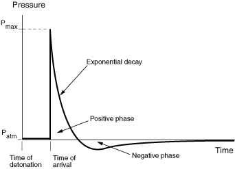
Unlike an acoustic wave, a blast wave corresponds to a shock wave with discontinuities
in pressure, density, etc. across the wave front. Figure 3 shows a typical pressure history of a blast wave.
Figure 3. Pressure history of a blast wave.
The CONWEP model uses a scaled distance based on the
distance of the loading surface from the source of the explosion and the amount of
explosive detonated. For a given scaled distance, the model provides the following
empirical data: the maximum overpressure (above atmospheric), the arrival time, the
positive phase duration, and the exponential decay coefficient for both the incident
pressure and the reflected pressure. Using these parameters, the entire time history of
both the incident pressure and reflected pressure as shown in Figure 3 can be constructed. Use of a standoff point is not required.
The total pressure, , on a surface due to the blast wave is a function of the incident
pressure, , the reflected pressure, , and the angle of incidence, , which is defined as the angle between the normal of the loading
surface and the vector that points from the surface to the explosion source. The total
pressure is defined as
The air blast loading due to the total pressure can be scaled using a magnitude scale
factor.
A detonation time can be specified if the explosion does not occur at the start of the
analysis. The detonation time needs to be given in total time; see Conventions for a
description of the time convention. The arrival time at a location is defined as the
elapsed time for the wave to arrive at that location after detonation.
The CONWEP empirical data are given in a specific set
of units, which must be converted to the units used in the analysis. You will need to
specify multiplying factors for conversion of these units to
SI units. For the specification of the mass of the
explosive in TNT equivalence, you can choose any
convenient mass unit, which can be different from the mass unit used in the analysis.
For computation of the pressure loading, you will need to specify multiplying factors
for conversion of length, time, and pressure units used in the analysis to
SI units. Some typical conversion multiplier values
are given in Table 3.
Table 3. Multipliers used in conjunction with the CONWEP
model for conversion to SI units.
Quantity
Unit
SI Unit
Multiplier for conversion to
SI
Mass
ton
kg
1000
Mass
lb
kg
0.45359
Length
mm
m
0.001
Length
ft
m
0.3048
Time
msec
sec
0.001
Pressure
MPa
Pa
106
Pressure
psi
Pa
6894.8
Pressure
psf
Pa
47.88
For any given amount of explosive, the CONWEP
empirical data are valid only within a range of distances from the source. The minimum
distance at which the data are valid corresponds to the charge radius. Thus, the
analysis terminates if the distance of any part of the loading surface from the source
is less than the charge radius. For distances that are larger than the maximum valid
range, linear extrapolation is used up to an extended maximum range where the reflected
pressure decreases to zero. No loading is applied beyond the extended maximum range.
The CONWEP empirical data do not account for shadowing
by intervening objects or for any effects due to confinement. In the definition of
incident wave interaction using the CONWEP model, you
cannot use incident wave reflection.
Use the following options to specify loading effects due to explosion in air using
the CONWEP charge property definition:
Interaction module: Create Interaction Property: Name: wave property name and Incident wave: Definition: Air blast or Surface blast: enter data defining the CONWEP charge
Interaction module: Create Interaction: Name: incident wave name and Incident wave: select the source point: CONWEP (Air/Surface blast): select the region: CONWEP Data: enter data defining the time of detonation and magnitude scale factor
Modifying or Removing Incident Wave Loads
Only the incident wave loads that are specified in a particular step are applied in that
step; previous definitions are removed automatically. Consequently, incident wave loads
that are active during two subsequent steps should be specified in each step. This is akin
to the behavior that can be specified for other types of loads by releasing any load of
that type in a step (see About Loads).
Alternative Incident Wave Loading Interface
In general, the concepts of the alternative incident wave loading interface are the same
as the preferred interface; however, the syntax for specifying the incident wave loading
is different. The preferred incident wave loading interface is
supported in Abaqus/CAE. The alternative interface is not supported in Abaqus/CAE. For conceptual information, see Incident Wave Loading due to External Sources.
Prescribing the Geometric Properties and the Speed of the Incident Wave
(Alternative Interface)
The alternative incident wave loading interface is not supported in Abaqus/CAE.
Defining the Time History of the Source Pulse (Alternative Interface)
Conceptually, the alternative interface is the same as the preferred interface;
however, the usages are different. For conceptual information, see Defining the Amplitude of the Source Pulse.
Input File Usage
Use the following option to define the time history in terms of fluid pressure
values:
INCIDENT WAVE, PRESSURE AMPLITUDE=amplitude data table namesolid or fluid surface name, reference magnitude
Use the following option to define the time history in terms of fluid particle
acceleration values:
To define the bubble dynamics using a model internal to Abaqus, you can specify a bubble amplitude. Use of the bubble loading amplitude is generally
similar to the use of any other amplitude in Abaqus.
The alternative incident wave loading interface is not supported in Abaqus/CAE.
Specifying the Reflection Effects (Alternative Interface)
Conceptually, the alternative interface is the same as the preferred interface;
however, the usages are different. For conceptual information, see Specifying the Reflection Effects.
Input File Usage
Use the following option in conjunction with the INCIDENT WAVE option to define
an incident wave reflection plane:
The alternative incident wave loading interface is not supported in Abaqus/CAE.
Modeling Incident Wave Loading on a Moving Structure (Alternative
Interface)
To model the effect of rigid motion of a structure such as a ship during the incident
wave loading history, the standoff point can have a specified velocity. It is assumed
that the entire fluid-solid model is moving at this velocity with respect to the source
point during the loading and that the speed of the model's motion is low compared to the
speed of propagation of the incident wave.
Input File Usage
INCIDENT WAVE PROPERTY, NAME=wave property namedata line to specify the velocity of the standoff point
Abaqus/CAE Usage
The alternative incident wave loading interface is not supported in Abaqus/CAE.
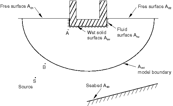
Example: Submarine Close to the Free Surface
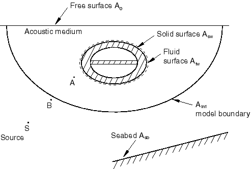
The problem shown in Figure 4 has the following features: a free surface , seabed as a reflection plane, a wet solid surface , the fluid surface that is tied to the solid surface , and the boundary of the finite modeled domain separating the infinite acoustic medium.
The source S of the underwater explosion loading is also shown.
Figure 4. Incident wave loading on a submarine lying near a free surface.
Scattered Wave Solution
Here the scattered wave response in the acoustic medium is of interest along with that
of the structure to the incident wave loading. Cavitation in the fluid is not considered
in a scattered wave formulation. Similarly, the initial hydrostatic pressure in the
fluid is not modeled.
The zero dynamic acoustic pressure boundary condition on the free surface requires both
a “soft” reflection plane coinciding with the free surface and a zero scattered pressure boundary condition at the nodes on this
free surface. The incident wave loading is applied on the fluid surface, , and on the wet solid surface, . The incident wave loading can be only of pressure amplitude type
since the loading includes a solid surface.
A good location for the standoff node is marked as A in Figure 4. This node is in the fluid, close to the structure, and closer to incident wave
source S than any portion of the seabed or the free surface. The
standoff node's offset from the loaded surfaces is exaggerated for emphasis in the
figure.
The radiation condition is specified on the acoustic surface such that the scattered wave impinging on this boundary with the
infinite medium does not reflect back into the computational domain. The seabed is
modeled with an incident wave reflection plane on surface . The reflection loss at this seabed surface is modeled using an
impedance property.
If the response of the structure in the nonlinear regime is of interest, the initial
stress state in the structure should be established using Abaqus/Standard in a static analysis. The stress state in the structure is then imported into Abaqus/Explicit, and the loading on the solid surfaces causing the initial stress state is
respecified in the acoustic analysis.
The following template schematically shows some of the Abaqus input file options that are used to solve this problem using the scattered wave
formulation:
HEADING
…
SURFACE, NAME=
Data lines to define the acoustic surface that is wetting the solidSURFACE, NAME=
Data lines to define the solid surface that is wetted by the fluidSURFACE, NAME=
Data lines to define the acoustic surface separating the modeled region from the infinite mediumINCIDENT WAVE INTERACTION PROPERTY, NAME=IWPROP
AMPLITUDE, DEFINITION=TABULAR, NAME=PRESSUREVTIME
TIE, NAME=COUPLING
, STEP
** For an Abaqus/Standard analysis:
DYNAMIC
** For an Abaqus/Explicit analysis:
DYNAMIC, EXPLICIT
** Load the acoustic surface
INCIDENT WAVE INTERACTION, PRESSURE AMPLITUDE=PRESSUREVTIME,
PROPERTY=IWPROP
, source node, standoff node, reference magnitudeINCIDENT WAVE REFLECTIONData lines for the reflection plane over the seabed , seabed_QINCIDENT WAVE REFLECTIONData lines for a "soft" reflection plane over the free surface .
** Load the solid surface
INCIDENT WAVE INTERACTION, PRESSURE AMPLITUDE=PRESSUREVTIME,
PROPERTY=IWPROP
, source node, standoff node, reference magnitudeINCIDENT WAVE REFLECTIONData lines for the reflection plane over the seabed , seabed_QINCIDENT WAVE REFLECTIONData lines for a "soft" reflection plane over the free surface .BOUNDARY
** zero pressure boundary condition on the free surface
Set of nodes on the free surface , 8, 8, 0.0SIMPEDANCE, END STEP
Total Wave Solution
Here, the total wave response in the acoustic medium is of interest along with that of
the structure to the incident wave loading. Cavitation in the fluid might be included.
Similarly, a linearly varying initial hydrostatic pressure in the fluid can be
specified.
The zero dynamic acoustic pressure boundary condition on the free surfaces requires
only a zero pressure boundary condition at the nodes on this free surface. A reflection
plane should not be included along the free surface. The incident wave loading is
applied only on the fluid surface, , that separates the modeled region from the surrounding infinite
acoustic medium. No incident wave should be applied directly on the structure surfaces.
If the incident wave is considered planar, an acceleration-type amplitude can be used
with the incident wave loading. Otherwise, a pressure-type amplitude must be used with
the incident wave loading.
An ideal location for the standoff node depends on the type of amplitude used for the
time history of the incident wave loading. The location A shown in
Figure 4 can be used if the incident wave loading time history is of pressure amplitude type.
Otherwise, the location B that is just on the boundary and closer to the source S than any part of
either the seabed or the free surface can be used.
The nonreflecting impedance condition is specified on the acoustic surface, , such that the scattered part of the total wave impinging on this
boundary with the infinite medium does not reflect back into the computational domain.
The seabed is modeled with an incident wave reflection plane on the surface .
If the response of the structure in the nonlinear regime is of interest, the initial
stress state in the structure should be established using Abaqus/Standard in a static analysis. The stress state in the structure is then imported into Abaqus/Explicit, and the loading on the solid surfaces causing the initial stress state is
respecified in the acoustic analysis.
The following template schematically shows some of the input file options that are used
to solve this problem using the total wave formulation:
HEADING
…
ACOUSTIC WAVE FORMULATION, TYPE=TOTAL WAVEMATERIAL, NAME=CAVITATING_FLUID
ACOUSTIC MEDIUM, BULK MODULUSData lines to define the fluid bulk modulusACOUSTIC MEDIUM, CAVITATION LIMITData lines to define the fluid cavitation limit
…
SURFACE, NAME=
Data lines to define the acoustic surface that is wetting the solidSURFACE, NAME=
Data lines to define the solid surface that is wetted by the fluidSURFACE, NAME=
Data lines to define the acoustic surface separating the modeled region from the infinite mediumINCIDENT WAVE INTERACTION PROPERTY, NAME=IWPROP
AMPLITUDE, DEFINITION=TABULAR, NAME=PRESSUREVTIME
Data lines to define the pressure-time history at the standoff pointTIE, NAME=COUPLING
, INITIAL CONDITIONS, TYPE=ACOUSTIC STATIC PRESSUREData lines to define the initial linear hydrostatic pressure in the fluidSTEPDYNAMIC, EXPLICIT
** Load the acoustic surface
INCIDENT WAVE INTERACTION, PRESSURE AMPLITUDE=PRESSUREVTIME,
PROPERTY=IWPROP
, source node, standoff node, reference magnitudeINCIDENT WAVE REFLECTIONData lines for the reflection plane over the seabed , seabed_QBOUNDARY
** zero pressure boundary condition on the free surface
Set of nodes on the free surface , 8, 8, 0.0SIMPEDANCE, END STEP
Example: Submarine in Deep Water
This problem is similar to the previous example of a submarine close to the free surface
except for the following differences. There is no free surface in this problem; and the
fluid surface, , and the fluid medium completely enclose the structure. If the structure
is sufficiently deep in the water, hydrostatic pressure might be considered uniform
instead of varying linearly with depth. Under this assumption, the initial stress state in
the structure can be established with a uniform pressure loading all around it, if
desired. In addition, if the structure is sufficiently deep in the water, the hydrostatic
pressure might be significant compared to the incident wave loading; hence, the cavitation
in the fluid might not be of concern.
Example: Surface Ship
Here the effect of underwater explosion loading on a surface ship is of interest (see
Figure 5).
Figure 5. Modeling of incident wave loading on a surface ship.
This problem is similar to the previous example of a submarine close to the free surface
except for the following differences. The free surface of fluid is not continuous, and a
part of the structure is exposed to the atmosphere. A soft reflection plane coinciding
with the free surface is not used in this problem as in the submarine problems under the
scattered wave formulation. To be able to use the scattered wave formulation in this case,
the modeling technique is used in which the free surface is replaced with “structural
fluid” elements. A layer of fluid at the free surface is modeled using nonacoustic
elements such as membrane elements. These elements are coupled to the underlying acoustic
fluid using a mesh tie constraint. The nonacoustic elements have properties similar to the
fluid itself since these elements are replacing the fluid medium near the free surface and
should have a thickness similar to the height of the adjacent acoustic elements. Incident
wave loading with the scattered wave formulation must now be applied on these newly
created surfaces as well. This technique has the added advantage of providing the deformed
shape of the free surface under the loading.
The following template shows some of the Abaqus input file options used for this case:
HEADING
…
SURFACE, NAME=A01_structuralfluid
Data lines to define the "structural fluid" surfaceSURFACE, NAME=A01_acousticfluid
Data lines to define the adjacent acoustic fluid surfaceSURFACE, NAME=A02_structuralfluid
Data lines to define the "structural fluid" surfaceSURFACE, NAME=A02_acousticfluid
Data lines to define the adjacent acoustic fluid surfaceSURFACE, NAME=Asw_solid
Data lines to define the actual solid surface that is wetted by the fluidSURFACE, NAME=Asw_fluid
Data lines to define the actual acoustic surface that is adjacent to the structureSURFACE, NAME=
Data lines to define the acoustic surface separating the modeled region from the infinite mediumINCIDENT WAVE INTERACTION PROPERTY, NAME=IWPROP
AMPLITUDE, DEFINITION=TABULAR, NAME=PRESSUREVTIME
Data lines to define the pressure-time history at the standoff pointTIE, NAME=COUPLING
Asw_fluid, Asw_solid
A01_acousticfluid, A01_structuralfluid
A02_acousticfluid, A02_structuralfluidSTEP
** For an Abaqus/Standard analysis:
DYNAMIC
** For an Abaqus/Explicit analysis:
DYNAMIC, EXPLICIT
** Load the acoustic surfaces
INCIDENT WAVE INTERACTION, PRESSURE AMPLITUDE=PRESSUREVTIME,
PROPERTY=IWPROP
A01_acousticfluid, source point, standoff point, reference magnitudeINCIDENT WAVE REFLECTIONData lines for the reflection plane over the seabed , seabed_QINCIDENT WAVE INTERACTION, PRESSURE AMPLITUDE=PRESSUREVTIME,
PROPERTY=IWPROP
A02_acousticfluid, source point, standoff point, reference magnitudeINCIDENT WAVE REFLECTIONData lines for the reflection plane over the seabed , seabed_QINCIDENT WAVE INTERACTION, PRESSURE AMPLITUDE=PRESSUREVTIME,
PROPERTY=IWPROP
Asw_fluid, source point, standoff point, reference magnitudeINCIDENT WAVE REFLECTIONData lines for the reflection plane over the seabed , seabed_Q
** Load the solid surfaces
INCIDENT WAVE INTERACTION, PRESSURE AMPLITUDE=PRESSUREVTIME,
PROPERTY=IWPROP
A01_structuralfluid, source point, standoff point, reference magnitudeINCIDENT WAVE REFLECTIONData lines for the reflection plane over the seabed , seabed_QINCIDENT WAVE INTERACTION, PRESSURE AMPLITUDE=PRESSUREVTIME,
PROPERTY=IWPROP
A02_structuralfluid, source point, standoff point, reference magnitudeINCIDENT WAVE REFLECTIONData lines for the reflection plane over the seabed , seabed_QINCIDENT WAVE INTERACTION, PRESSURE AMPLITUDE=PRESSUREVTIME,
PROPERTY=IWPROP
Asw_solid, source point, standoff point, reference magnitude INCIDENT WAVE REFLECTIONData lines for the reflection plane over the seabed , seabed_QSIMPEDANCE, END STEP
Compared to the total wave formulation analysis of a submarine close to the free surface,
the following differences are noteworthy. As shown in Figure 5, the free surface with zero dynamic pressure boundary condition is now split into two
parts: and . The fluid surface wetting the ship () and the wetted ship surface (), which are tied together, do not encircle the whole structure. Besides
these differences, the modeling considerations for the surface ship problem are similar to
the total wave analysis of the submarine near the free surface.
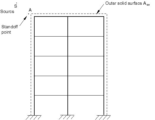
Example: Airblast Loading on a Structure
Here the effect of airblast (explosion in the air) loading on a structure is of interest
(see Figure 6).
Figure 6. Modeling of airblast loading on a structure.
Since the stiffness and inertia of the air medium are negligible, the acoustic medium is
not modeled. Rather the incident wave loading is applied directly on the structure itself.
The solid surface where the incident wave loading is applied is shown in Figure 6. Since the acoustic medium is not modeled, the total wave and the scattered wave
formulations are identical.
Example: Fluid Cavitation without Incident Wave Loading
You might be interested in modeling acoustic problems in Abaqus/Explicit where the loading is applied through either prescribed pressure boundaries or specified
pressure-conjugate concentrated loads. Choice of the scattered or the total wave
formulation is not relevant in these problems even when the acoustic medium is capable of
cavitation.