can be defined on solid, structural, rigid, surface, gasket, or acoustic elements;
can be deformable or rigid;
can be defined on any combination of elements in many cases;
can be defined on the exterior of any body; and
can be defined on the interior of any body that is modeled with continuum, shell,
membrane, surface, beam, pipe, truss, or rigid elements (e.g., to define a cross-section
through a body) either by simply cutting the body with a plane or by identifying the
elements and the corresponding interior facets.
You must assign a name to all element-based surfaces; this name can be used with various
features to define a contact model, a surface-based load, or a surface-based constraint. In
addition, you must specify the region of your model on which the surface is defined. In an
input file you can define element-based surfaces on element faces, edges, or ends. In Abaqus/CAE you can define element-based surfaces on geometric or element faces, edges, or ends.
The methods for defining surfaces depend on the underlying element type and are
discussed later in this section.
In an input file you need only specify an element number or element set name and all
exposed element faces of these elements (or “contact edges” of beam, pipe, and truss
elements) will be included in the surface. Optionally(and the only
available method in Abaqus/CAE), you can specify individual faces, edges, or ends, which allows you direct control
over which faces, edges, or ends are to be included in the surface.
An element number or element set name is specified as the first entry of each data
line. Optionally, an element face, edge, or end identifier can be specified as the second
entry on a data line. The face and edge identifiers used in Abaqus are discussed later in this section.
Multiple data lines can be used to define a surface. For example,
SURF_1 can be specified by the following input:
Any module except Sketch, Job, and Visualization: ToolsSurfaceCreate: Name:surface_name
General Restrictions on Element-Based Surfaces
Elements defining a single surface must satisfy the following rules, regardless of how the
surface is used in Abaqus:
Two-dimensional, axisymmetric, and three-dimensional elements cannot be mixed in the
same surface definition.
In Abaqus/Standard deformable elements cannot be combined with rigid elements to define a single
surface, but can be combined with other deformable elements that are part of a rigid
body (see Rigid Body Definition).
The following element types cannot be mixed with other element types in the same
surface definition:
Coupled thermal-electrical-structural elements
Coupled temperature-displacement elements
Heat transfer elements
Pore pressure elements
Coupled thermal-electrical elements
Acoustic finite or infinite elements
The axisymmetric solid Fourier elements with nonlinear, asymmetric deformation
(CAXA elements) cannot form element-based
surfaces.
The face identifier label is required to import an element-based surface from an input
file.
Surface Discretization
For element-based surfaces Abaqus uses a faceted geometry defined by the finite element mesh as the surface definition. The
surface in a coarse finite element model may not be a very good approximation for contact
modeling if the physical surface is curved. Therefore, sufficient mesh refinement must be
used to ensure that the faceted surface is a reasonable approximation of the curved physical
surface. Alternatively, some curved surface geometries may be more effectively modeled with
analytical rigid surfaces (see Analytical Rigid Surface Definition).
Creating Surfaces on Solid, Continuum Shell, and Cohesive Elements
There are three ways to define the facets of an element-based surface on solid, continuum
shell, and cohesive elements:
by instructing Abaqus to generate the “free surface” from the exposed faces of elements,
by specifying the particular faces for each element, and
in Abaqus/Explicit by instructing Abaqus to generate an interior surface from element faces that are not exposed (i.e., not
part of the “free surface” of the model).
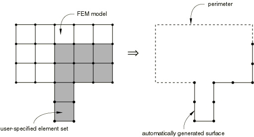
The automatic free surface generation approach is the simplest method of defining exterior
surfaces on solid elements. Specifying the element faces gives you exact control over which
element faces (any combination of exterior and interior faces) form the surface. Automatic
generation of an interior surface is the simplest method of defining interior surfaces on
solid elements (interior surfaces can be useful for modeling surface erosion due to element
failure).
It is possible to use all three approaches in the same surface definition when creating a
single surface.
Generating the Free Surface Automatically
You can define the facets of a surface by specifying a series of elements. The faces of
these elements that are on the exterior (free) surface of the model are included in the
surface definition.
When the free surface generation method is used to define surfaces, the specified
elements can be a mixture of continuum and structural elements.
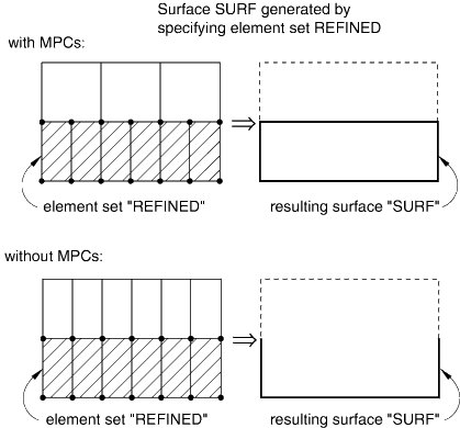
Multi-point constraints (General Multi-Point Constraints) involving nodes
on exposed surfaces are not taken into account during free surface generation, which can
result in faces that are not on the exterior of a body being included in surface
definitions. For example, the nodes of the elements in element set
REFINED shown in Figure 1 are used in linear, mesh-refinement constraints. The surfaces generated with and
without multi-point constraints are shown in Figure 1.
Figure 1. Effect of multi-point constraints on automatic surface generation.
Input File Usage
SURFACE, NAME=surface_name, TYPE=ELEMENTelement number or element set,
For example, if the name of the shaded element set in the figure below is
ESETA, the surface named
ASURF is specified by
The automatic free surface generation method is not supported in Abaqus/CAE.
Special Treatment of Cohesive Elements for Automatic Free Surface
Generation
The definition of exposed faces of elements for the purpose of automatic free surface
generation has the following unique aspects regarding cohesive elements:
Faces of non-cohesive elements along an interface of shared nodes with cohesive
elements are considered exposed.
The top and bottom faces of all cohesive elements are considered exposed; side
faces of cohesive elements are never considered exposed.
Creating Surface Facets by Specifying Solid, Continuum Shell, and Cohesive Element
Faces
You can define the facets of a surface by identifying the element faces that should be
included in the surface definition.
Element face numbers are defined in About the Element Library. Table 1 contains a list of valid face identifiers for all solid, continuum shell, and cohesive
elements. The face identifier can refer to individual elements or to entire element sets.
Table 1. Surface definition face identifier labels for solid, continuum shell, and cohesive
elements.
SURFACE, NAME=surface_name, TYPE=ELEMENTelement number or set, face identifier
When you specify the element faces to define surfaces, the specified elements cannot
be a mixture of continuum and structural elements; however, each data line of the
surface definition can refer to different element types.
Abaqus/CAE Usage
Any module except Sketch, Job, and Visualization: ToolsSurfaceCreate: Name:surface_name, pick faces in viewport
Generating an Interior Surface Automatically
Abaqus/Explicit provides two approaches to define eroding surfaces for a solid element mesh for use in
general contact (see Modeling Surface Erosion). The recommended approach dynamically evolves the list of surface faces to correspond
to currently exposed faces of elements that have not failed. The other approach statically
creates all of the possible interior faces and tracks which of these faces are active.
These methods give approximately the same results, but the dynamically evolving approach
often uses much less memory and tends to be faster.
Elements that do not have any interior faces by definition (such as shell elements, beam
elements, pipe elements, and membrane elements) are ignored.
Multi-point constraints are not taken into account when generating interior surfaces.
This can result in faces that are on the interior of a body being excluded from the
surface definition.
Generating a Dynamically Evolving Eroding Surface
In this recommended approach the surface evolves to correspond to the currently exposed
faces of the specified element set. At a given point in the simulation, this surface may
be a combination of originally exposed faces and faces that were originally in the
interior.
Input File Usage
SURFACE, NAME=surface_name, TYPE=ELEMENTelement number or element set, ERODING
Abaqus/CAE Usage
Generating a dynamically evolving eroding surface is not supported in Abaqus/CAE.
Generating a Static Interior Surface
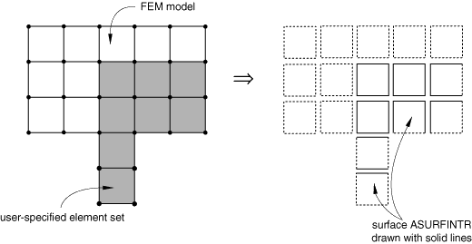
In this approach all faces of the specified elements that are not on the exterior
(free) surface of the model are included in the surface definition. Abaqus tracks which of these faces are currently exposed. The automatic generation of an
interior surface is equivalent to constructing a surface consisting of all faces of the
elements and then subtracting the free surfaces of those elements. A static interior
surface is less convenient (because faces on the original exterior must be included
separately) and less efficient (due to memory allocation for all faces of all elements
rather than just currently active faces) to use than a dynamically evolving eroding
surface.
Input File Usage
SURFACE, NAME=surface_name, TYPE=ELEMENTelement number or element set, INTERIOR
For example, if the name of the shaded element set in the figure below is
ESETA, the surface named
ASURFINTR (the elements in the figure have been
reduced in size to differentiate faces that share the same nodes) is specified by
Any module except Sketch, Job, and Visualization: ToolsSurfaceCreate: Name:surface_name, Type: Mesh; pick element faces or edges from an interior surface
You can use the selection tools to select from an interior entity of a model; see
Selecting interior surfaces.
Creating Surfaces on Structural, Surface, and Rigid Elements
There are five ways to define surfaces on structural, surface, and rigid elements:
You can create a single-sided surface with a well-defined orientation by indicating
either the top or bottom surface of each specified element.
You can create a double-sided surface by specifying only the elements and letting Abaqus generate the “free surface” from the exposed faces.
You can create an edge-based surface.
You can create a cross-section surface on the ends of beam, pipe, and truss elements.
You can create a three-dimensional curve-type surface along the length of beam, pipe,
and truss elements by specifying only the elements and letting Abaqus generate the “free surface.”
It is possible to use any or all of the above approaches in the same surface definition as
long as it makes sense in the use of that surface with other features in Abaqus. Table 2 contains a list of valid face and edge identifiers for structural, surface, and rigid
elements.
Table 2. Surface definition face and edge identifier labels for structural, surface, and rigid
elements.
END1, END2; must use
node-based surfaces with the contact pair algorithm in Abaqus/Explicit.
STRI3S3(R)(S)M3D3
STRI65R3D3
SPOS,
SNEG,E1,
E2, E3
ACIN2D2ACINAX2
ACIN2D3ACINAX3
SPOSE1,
E2
S4(R)(S)(W)(5)S9R5M3D4(R)
S8R5(T)R3D4
SPOS,
SNEG,E1,
E2, E3,
E4
ACIN3D3
ACIN3D6
SPOSE1,
E2, E3
ACIN3D4
ACIN3D8
SPOSE1,
E2, E3,
E4
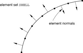
Defining Single-Sided Surfaces
You can define a single-sided surface on the positive or negative face of structural,
surface, or rigid elements. The positive face is defined as the one in the direction of
the positive element normal, and the negative face is defined as the one in the direction
opposite to the element normal. The definition of the element normal for all elements is
given in About the Element Library.
You must ensure that all of the specified elements have their normals oriented
consistently. If they are oriented as shown in Figure 2, the surface normals will reverse direction as the surface is traversed and improper
results may occur when the surface is used with features requiring an orientation such as
distributed surface loads.
Figure 2. Inconsistent orientation of structural element normals can result in an invalid
surface.
Further, an error message will be issued and the analysis will terminate if this
condition is detected for surfaces used with mesh tie constraints in Abaqus/Standard or with contact pairs. To correct the surface orientations in this figure, two separate
element sets with different face identifiers should be used.
Input File Usage
Use the following option to define a surface on the positive face of a structural,
surface, or rigid element:
SURFACE, NAME=surface_name, TYPE=ELEMENTelement number or element set, SPOS
Use the following option to define a surface on the negative face of a structural,
surface, or rigid element:
SURFACE, NAME=surface_name, TYPE=ELEMENTelement number or element set, SNEG
For example, single-sided surfaces on the positive faces of the elements in element
set SHELL can be defined using input similar to
Any module except Sketch, Job, and Visualization: ToolsSurfaceCreate: Name:surface_name, pick face in viewport, click mouse button 2, and specify the side of the selected face
Defining Double-Sided Surfaces
You can create double-sided surface facets on three-dimensional shell, membrane, surface,
and rigid elements using the automatic surface facet generation approach (i.e., specifying
only the element numbers or sets). Some applications that refer to surfaces do not allow
the use of double-sided surfaces: examples include contact pairs in Abaqus/Standard and features requiring an oriented surface such as distributed surface loads. When
double-sided surfaces can be used, they are often preferred to single-sided surfaces. In
some applications, such as when defining the contact domain for general contact, it does
not matter whether single- or double-sided surfaces are used.
When double-sided surfaces are used with contact pairs in Abaqus/Explicit, the normals of all the underlying elements do not need to have a consistent positive
orientation: Abaqus/Explicit will define the contact surface such that its facets have consistent normals, even if
the underlying elements do not have consistent normals. The facet normals will be the same
as the element normals if the element normals are all consistent; otherwise, an arbitrary
positive orientation is chosen for the surface. The positive orientation is significant
only with respect to the sign of the contact pressure output variable for the contact pair
algorithm, CPRESS (see Output).
Although contact is enforced unconditionally on both sides of a surface when self-contact
is used with contact pairs, contact is enforced on both sides of a surface used in
two-body contact only when that surface is double-sided (if allowed). The use of
single-sided surfaces with contact pairs is sometimes desirable: the resolution of large
initial overclosures in contact pairs is more robust with single-sided surfaces than with
double-sided surfaces (see Contact Initialization for Contact Pairs in Abaqus/Explicit). However,
single-sided contact is generally more limiting than double-sided contact; it may cause an
analysis to fail due to excessive element distortion or not enforce the contact conditions
realistically if a secondary node unexpectedly moves behind a main surface. This condition
can occur, for example, when large deformations or rigid-body motions are present or due
to complex tool shapes in a forming analysis.
Input File Usage
Use the following option to define a double-sided surface on three-dimensional
shell, membrane, surface, or rigid elements in Abaqus/Explicit:
SURFACE, NAME=surface_name, TYPE=ELEMENTelement number or element set,
For example, double-sided surfaces on the elements in element set
SHELL can be defined using input similar to
Any module except Sketch, Job, and Visualization: ToolsSurfaceCreate: Name:surface_name, pick face in viewport, click mouse button 2, and choose Both sides
Defining Edge-Based Surfaces
You can define an edge-based surface on three-dimensional shell, membrane, surface, or
rigid elements by specifying the individual edges. Alternatively, you can specify that
perimeter edges are used to form the surface. It is possible to use both methods in the
same surface definition when creating a single surface.
Input File Usage
Use the following option to specify the individual edges that form the
surface:
SURFACE, NAME=surface_name, TYPE=ELEMENTelement number or element set, edge identifier
The individual edge identifiers used in Abaqus are listed in Table 2.
Use the following option to specify that all the edges of the elements that are on
the exterior (free) surface of the model are used to form the surface:
SURFACE, NAME=surface_name, TYPE=ELEMENTelement number or element set, EDGE
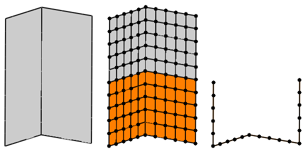
For example, consider a shell with a fold on the left side of the figure below. If
the shell mesh is as shown in the middle of this figure and element set shaded orange is
named ESETA, the edge-based surface named
ESURF comprised of perimeter edges shown on the right
could be specified by the following input:
Any module except Sketch, Job, and Visualization: ToolsSurfaceCreate: Name:surface_name, pick edges in viewport
In Abaqus/CAE you can specify that all the edges of the elements that are on the exterior (free)
surface of the model are used to form the surface by directly picking all the free edges
in the viewport.
Defining a Surface over the Cross-Section at the Ends of Beam, Pipe, and Truss
Elements
To define a surface over the cross-section of beam, pipe, or truss elements, you must
specify the end on which the surface is defined. Surfaces created on the ends of these
elements can be used only for integrated output request (see Integrated Output) and integrated output section (see Integrated Output Section Definition) definitions.
Input File Usage
Use the following option to define a surface over the cross-section of a beam, pipe,
or truss element:
SURFACE, NAME=surface_name, TYPE=ELEMENTelement number or element set, END1 or END2
Abaqus/CAE Usage
Any module except Sketch, Job, and Visualization: ToolsSurfaceCreate: Name:surface_name, pick three-dimensional wire region in viewport, click mouse button 2, and choose End (Magenta) or End (Yellow)
Defining a Surface along the Length of Three-Dimensional Beam, Pipe, and Truss
Elements
You cannot specify the faces to define a surface along the length of three-dimensional
beams, pipes, or trusses because their element connectivity cannot define a unique element
or surface normal. Instead, you must specify that Abaqus should generate a surface for these elements. Therefore, the use of surfaces along the
length of these elements is restricted.
In Abaqus/Standard element-based surfaces created along the length of three-dimensional beam, pipe, or
truss elements can be used with the general contact algorithm or tie constraints. In a
contact pair simulation, they can be used only as secondary surfaces. There are several
advantages to using an element-based surface rather than a node-based surface when
modeling contact in Abaqus/Standard with three-dimensional beams, pipes, or trusses:
The default local tangent directions are parallel and orthogonal to the element axis.
Abaqus/Standard calculates the contact results as contact forces per unit length rather than just
contact forces.
It can be easier to define an element-based surface than a node-based surface.
In Abaqus/Standard a surface definition is not allowed for cases where three or more three-dimensional
beams, pipes, or trusses are joined at a common node because of the lack of uniquely
defined element tangents.
In Abaqus/Explicit element-based surfaces created along the length of three-dimensional beam, pipe, or
truss elements can be used only with the general contact algorithm or tie constraints. To
define contact for these elements using the contact pair algorithm, the nodes forming the
beam, pipe, or truss elements can be included in a node-based surface definition (Node-Based Surface Definition) and a contact pair can be defined for this
node-based surface and a non-node-based surface.
Surfaces along the length of three-dimensional beam, pipe, or truss elements cannot be
used to prescribe a distributed surface load since the loading direction is not unique.
Input File Usage
Use the following option to define a surface along the length of a three-dimensional
beam, pipe, or truss element:
SURFACE, NAME=surface_name, TYPE=ELEMENTelement number or element set,
Abaqus/CAE Usage
Any module except Sketch, Job, and Visualization: ToolsSurfaceCreate: Name:surface_name, pick three-dimensional wire region in viewport, click mouse button 2, and choose Circumferential
Surfaces along the Length of Two-Dimensional Beam, Pipe, and Truss Elements
Surfaces created along the length of two-dimensional beam, pipe, and truss elements can
be used as main surfaces in a contact pair simulation because the underlying elements have
unique element normals that lie in the plane of the model. These surfaces can also be used
to prescribe distributed surface loads.
Shell, Membrane, or Rigid Element Thickness and Shell Offset
Some applications that refer to surfaces will account for underlying element thicknesses
and any offset of the midsurface relative to the reference surface for surfaces based on
shell, membrane, or rigid elements. For example, all of the contact algorithms available
in Abaqus/Explicit can account for these effects. Of the contact algorithms available in Abaqus/Standard, only the surface-to-surface small-sliding contact formulation can account for these
effects. See the following sections for additional details on applications that can
account for surface thickness and offset:
When surfaces are defined on gasket elements, automatic surface facet generation cannot be
used because only the top and bottom element faces can be used to create surfaces (see About Gasket Elements). Abaqus/Standard cannot create surfaces on gasket link elements since the top and bottom surfaces are each
reduced to a single node. For other gasket elements you must specify the top and bottom
surfaces directly. The positive face of the element is in the thickness direction of the
element. The definition of the thickness direction of all gasket elements is given in Defining the Gasket Element's Initial Geometry. The negative face
is defined as the face in the direction opposite to the thickness direction of the element.
Input File Usage
Use the following option to define a surface on the positive face of a gasket
element:
SURFACE, NAME=surface_name, TYPE=ELEMENTelement number or element set, SPOS
Use the following option to define a surface on the negative face of a gasket
element:
SURFACE, NAME=surface_name, TYPE=ELEMENTelement number or element set, SNEG
For example, single-sided surfaces on the positive faces of the elements in element
set GASKET can be defined using input similar to
Any module except Sketch, Job, and Visualization: ToolsSurfaceCreate: Name:surface_name, pick top or bottom faces in viewport
Surfaces on Three-Dimensional Gasket Line Elements
There are several advantages to using an element-based surface rather than a node-based
surface when modeling contact in Abaqus/Standard with three-dimensional gasket line elements:
The local tangent directions are parallel and orthogonal to the gasket line element,
which is useful for output purposes and for anisotropic friction definition.
Abaqus/Standard calculates the contact results as contact forces per unit length rather than just
contact forces.
Surfaces created on three-dimensional gasket line elements can be used only as secondary
surfaces because Abaqus/Standard cannot form unique normals for these surfaces.
Creating Interior Cross-Section Surfaces
To study the “force-flow” through various paths in a model, you must create interior
surfaces that cut through one or more components (similar to a cross-section) so that you
can request integrated output of the total force transmitted across these surfaces (see
Requesting Integrated Output for “Force-Flow” Studies). Abaqus provides a simple method to create such an interior surface over the element facets,
edges, or ends by cutting through a region of the model with a plane. The region can be
identified using one or more element sets. If no element sets are specified, the region
consists of the whole model. The cutting plane is defined by specifying the coordinates of a
point on the plane and a vector normal to the plane. Alternatively, the cutting plane can be
defined by specifying the global node numbers of point a on the plane
and point b that lies off the cutting plane with the normal determined
as the vector from point a to point b. Abaqus then automatically forms a surface close to the specified cutting plane by selecting the
element facets, edges, or ends of the continuum solid, shell, membrane, surface, beam, pipe,
truss, or rigid elements in the selected region. The surface generated in this manner is an
approximation for the cutting plane.
Multi-point mesh constraints are ignored while generating the interior surface based on the
cutting plane; therefore, the result may be a surface that is not continuous if these
constraints stitch disjointed meshes together in a region that is cut by the cutting
plane. When the cutting plane intersects a beam, pipe, or truss
element, the entire element is shown in the Visualization module of Abaqus/CAE as being part of the surface. However, if this surface is used for integrated output,
only the element nodal forces from the element end that lies on the positive side as defined
by the normal to the cutting plane are included in the integrated output. Point mass
and rotary elements, connector elements, spot welds, and spring elements will not be part of
the generated surface even if they are cut by the cutting plane.
Input File Usage
Use the following option to define the cutting surface by specifying coordinates of a
point on the plane and a vector normal to the plane:
Interior cross-section surfaces are not supported in Abaqus/CAE.
Whole-Model Free Surface in an Abaqus/Explicit Input File
In an Abaqus/Explicit input file you can create a surface containing the exposed faces of all elements (and
“contact edges” of beam, pipe, and truss elements) in the model except cohesive elements by
specifying a blank element set name and a blank face identifier. This “free” surface of the
model can be used as the base surface for the cropping and combining operations; without
modifications this surface is similar to the default all-inclusive surface commonly used in
general contact (see About General Contact in Abaqus/Explicit).
The whole-model automatic free surface generation method is not supported in Abaqus/CAE.
Trimming the Perimeter of an Open Surface
An “open” surface is one that has ends in two dimensions or an outside edge in three
dimensions. The ends of a two-dimensional surface and the edge of a three-dimensional
surface are called the surface's “perimeter.” Since Abaqus allows a surface to be defined as only a part of the surface of a body, it may have a
perimeter even though it is defined on a closed body. Abaqus automatically performs surface “trimming” on solid element meshes. You can change the
default setting when a surface is created, providing some basic control over the extent of
surfaces.
Surface trimming:
is a recursive procedure that removes undesirable convex corners near the perimeter of
an open surface (see the example below for details);
has no effect on closed surfaces (ones with no ends or edges);
is performed automatically, unless the surface is used as a main surface in a
finite-sliding simulation in Abaqus/Standard or the surface is used with the contact pair algorithm in Abaqus/Explicit;
can be used only for external surfaces on solid element meshes (either specified
surfaces or automatically generated free surfaces); and
has no effect on surfaces used with the contact pair algorithm in Abaqus/Explicit.
Input File Usage
Use the following option to suppress automatic surface trimming:
Automatic surface trimming cannot be suppressed in Abaqus/CAE.
The Effect of Surface Trimming
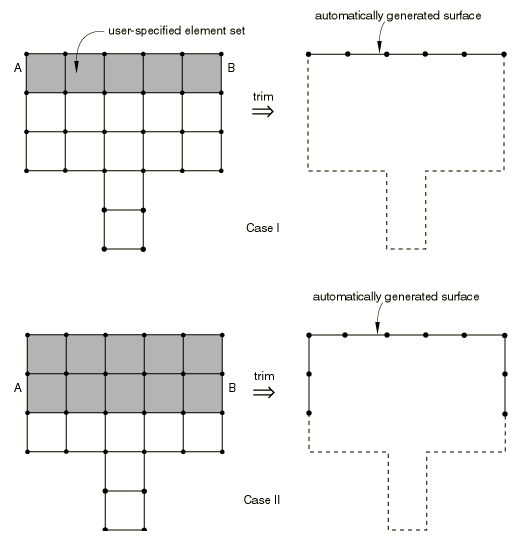
The effect of surface trimming is best explained by means of an example. Figure 3 illustrates the effect of trimming for two different surfaces defined on the same
simple two-dimensional mesh.
Figure 3. Case I: Faces A and B are removed when
trimming is done since one node of each of the faces is an end node and the other is a
corner node. Case II: Faces A and
B are not removed when trimming is done since one node of each of
the faces is an end node but the other is not a corner node.
In Case I the surface definition consists of a single layer of elements on the perimeter
of the model. Using automatic surface facet generation, the resulting default surface
(curve) includes the vertical element faces A and
B since these faces lie on the perimeter of the model. Trimming the
default surface created in Case I eliminates faces A and
B since their presence results in the two spurious corners near the
perimeter of the curve.
Abaqus uses a special criterion in deciding to remove faces A and
B from the original open curve. A face is removed if one of its end
nodes is an endpoint and either of the following is true: another face node is a node on
an element corner belonging to the curve or the face normal differs by more than 30° from
the normal of an adjacent face also belonging to the curve. To be a node on an element
corner belonging to the curve means to be a node on two different faces of the same
element, both of which are part of the curve. The face removal criterion is applied
recursively to the curve definition until all corners on or near the perimeter of the
curve have been removed. This procedure is generalized for three-dimensional surface
definitions.
In Case II in Figure 3 trimming would not result in the elimination of faces A and
B because neither of the endpoints of these two faces meets the
criterion described above.
Why Abaqus Will, by Default, Trim Most Surfaces
Trimming of surfaces used for application of distributed loads is usually desired since
loads are normally applied to specific sides of a body. Any surface that is used for
application of a distributed load will, by default, be trimmed.
In Abaqus/Standard trimming the secondary surface in contact or interaction simulations results in more
accurate estimates of the contact pressures, heat fluxes, and electrical current densities
along the perimeter of the surface. Any surface that is used as a secondary surface in a
contact or interaction simulation will, by default, be trimmed. If the secondary surface
is left untrimmed, the nodes at the corners of the surface will be assigned additional
contact area from the element faces around the corners that may never be involved in the
interaction between the surfaces. This additional contact area introduces errors into the
estimates of the contact output variables at those nodes. Main surfaces in small-sliding
simulations will, by default, be trimmed; Abaqus/Standard will normally form a better approximate surface. However, main surfaces in
finite-sliding contact simulations will, by default, be left untrimmed, and they should
extend far enough away from all expected regions of contact. This practice protects
against the possibility of the secondary surface nodes sliding off the main surface (see
Common Difficulties Associated with Contact Modeling in Abaqus/Standard).