The paperboard plasticity model provides a general capability for modeling
paperboard materials that undergo permanent deformation.
The paperboard plasticity model:
consists of the combination of constitutive models for the in-plane, thickness,
and out-of-plane shear responses, which Abaqus assumes to be decoupled;
can be used to model the anisotropic in-plane elastic-plastic response;
considers the out-of-plane behavior to be linear elastic in tension and
elastic-plastic in compression;
can be used to model the out-of-plane shear plastic response; and
must be used with the orthotropic linear elastic material model (Linear Elastic Behavior) for which the in-plane and
out-of-plane behaviors are decoupled ( and ).
Paperboard materials are made with fiber and water. During the manufacturing process,
most of the fibers are oriented in the machine direction
(MD), and almost no fibers are oriented in the
thickness direction (ZD). These orientations mean
that the mechanical response of paperboard material is orthotropic. The two in-plane
principal directions are along the machine (MD) and
cross (CD) directions, and the third principal
direction is along the thickness (ZD) direction, as
shown in Figure 1.
Figure 1. Principal directions of a paperboard material.
In-plane Response
The in-plane stress-strain response of paperboard is highly dependent on the fiber
directions (see Figure 2). The elastic
in-plane response of the paperboard model can be defined in the form
where , , , and are the engineering constants.
Figure 2. Typical stress-strain response of paper board under uniaxial tension in MD,
MD-CD, and CD directions.
Yield Criteria
A yield criterion was proposed by Xia (Xia, 2002):
The yield surface normals are defined by the plastic "Poisson's
ratios" fitted from test data as shown in Figure 3:
where and are the plastic strains in the
MD direction when tension/compression load
is applied and and are the plastic strains in the
CD direction when tension/compression load
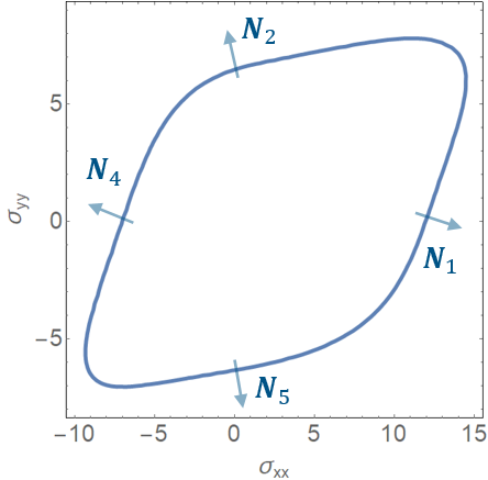
is applied.Figure 3. Schematic representation of plastic Poisson's ratios. Figure 4 shows a typical yield surface that is constructed by six subsurfaces (listed
in Table 1). Figure 4. Yield surfaces as proposed by Xia.
Table 1. In-plane Yield Subsurfaces.
Yield Plane
Stress State
1
Tension in MD
direction
2
Tension in CD
direction
3
Positive shear in MD-CD
direction
4
Compression in MD
direction
5
Compression in CD
direction
6
Negative shear in MD-CD
direction
The exponent 2k is a positive even integer, which determines the
smoothening between the planes as shown in Figure 5—the corners are sharper with larger values of the exponent. is the yield stress of the th subsurface, which is a function of the equivalent plastic
strain . The parameter is defined as
Figure 5. Yield surface proposed by Xia when .
Hardening
The yield stress of the th subsurface can be expressed as
where , , and are the hardening parameters. is the effective plastic strain, which evolves with an
associated flow rule
Input File Usage
Use the following option to specify the in-plane plastic "Poisson's
ratios":
The stress component is considered to be dependent only on the deformation in the
thickness direction:
where is the elastic modulus in the thickness direction. , , and are the total strain, elastic strain, and plastic strain in the
thickness direction, respectively. is the original void to solid ratio. and are parameters for the elastic behavior in
ZD.
The yield criterion is defined as:
with the hardening function defined as:
where , , and are the hardening parameters.
Input File Usage
Use the following option to specify the elastic
ZD compression response:
The paperboard plasticity model can be used with plane stress and 3D continuum
elements that include mechanical behavior (elements that have displacement degrees
of freedom).
References
Xia, Q.S., “Mechanics of Inelastic Deformation and Delamination in Paperboard,” Ph.D. Thesis, Massachusetts Institute of Technology, Cambridge, MA, 2002