is a phenomenological model that captures the mechanical response of a woven fabric made
of yarns in the fill and the warp directions;
is valid for materials that exhibit two “structural” directions that may not be
orthogonal to each other with deformation;
defines the local fabric stresses as a function of change in angle between the fibers
(shear strain) and the nominal strains along the yarn directions;
allows for the computation of local fabric stresses based on test data or through user
subroutine VFABRIC, which can be used to
define a complex constitutive model; and
requires that geometric nonlinearity be accounted for during the analysis step (General and Perturbation Procedures), since it is
intended for finite-strain applications.
The fabric material model defined based on test data:
assumes that the responses along the fill and the warp directions are independent of each
other and that the shear response is independent of the direct response along the yarns;
can include separate loading and unloading responses;
can exhibit nonlinear elastic behavior, damaged elastic behavior, or elastic-plastic type
behavior with permanent deformation upon complete unloading;
can deform elastically to large tensile and shear strains; and
can have properties that depend on temperature and/or other field variables.
Woven fabrics are used in a number of engineering applications across various industries,
including such products as automobile airbags; flexible structures like boat sails and
parachutes; reinforcement in composites; architectural expressions in building roof
structures; protective vests for military, police, and other security circles; and
protective layers around the fuselage in planes.
Woven fabrics consist of yarns woven in the fill and the warp directions. The yarn is
crimped, or curved, as it is woven up and down over the cross yarns. The nonlinear
mechanical behavior of the fabric arises from different sources: the nonlinear response of
the individual yarns, the exchange of crimp between the fill and the warp yarns as they are
stretched, and the contact and friction between the yarns in cross directions and between
the yarns in the same direction. In general, the fabric exhibits a significant stiffness
only along the yarn directions under tension. The tensile response in the fill and warp
directions may be coupled due to the crimp exchange mentioned above. Under in-plane shear
deformation, the fill and warp direction yarns rotate with respect to each other. The
resistance increases with shear deformation as lateral contact is formed between the yarns
in each direction. The fabrics typically have negligible stiffness in bending and in-plane
compression.
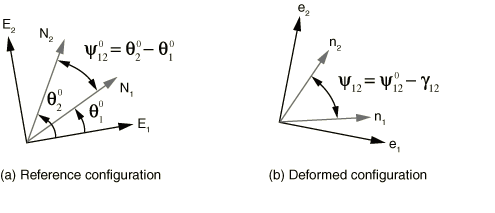
The behavior of woven fabrics is modeled phenomenologically in Abaqus/Explicit to capture the nonlinear anisotropic behavior of the fabric. The planar kinematic state
of a given fabric is described in terms of the nominal direct strains in the fabric plane
along the fill and the warp directions and the angle between the two yarn directions. The
material orthogonal basis and the yarn local directions are illustrated in Figure 1 showing the reference and the deformed configurations.
Figure 1. Fabric kinematics
The engineering nominal shear strain, , is defined as the change in angle, between the two yarn directions going from the reference to the deformed
configuration. The nominal strains along the yarn directions and in the deformed configuration are computed from the respective yarn
stretch values, and . The corresponding nominal stress components , and are defined as the work conjugate of the above nominal strains. The fabric
nominal stress, , is converted by Abaqus to the Cauchy stress, ; and the subsequent internal forces arising from the fabric deformation
are computed. You can obtain output of the fabric nominal strains, the fabric nominal
stresses, and the regular Cauchy stresses. The relationship between the Cauchy stress, , and the nominal stress, , is
where is the volumetric Jacobian.
Either experimental data or a user subroutine, VFABRIC, can be used to characterize
the Abaqus/Explicit fabric material model, providing the nominal fabric stress as a function of the nominal
fabric strains. The user subroutine allows for building a complex material model taking into
account both the fabric structural parameters such as yarn spacing, yarn cross-section
shape, etc. and the yarn material properties. The test data–based fabric model makes some
simplifying assumptions but allows for nonlinear response including energy loss. The two
models are presented below in detail. Both models capture the wrinkling of fabric under
compression only in a smeared fashion.
The fabric material model based on test data assumes that the responses along the fill and
the warp directions are independent of each other and that the shear response is independent
of the direct response along the yarn. Hence, each component-wise fabric stress response
depends only on the fabric strain in that component. Thus, the overall behavior of the
fabric consists of three independent component-wise responses: namely, the direct response
along the fill yarn to the nominal strain in the fill yarn, the direct response along the
warp yarn to the nominal strain in the warp yarn, and the shear response to the change in
angle between the two yarns.
Within each component you must provide test data defining the response of the fabric. To
fully define the fabric response, the test data must cover all of the following attributes:
Within a component, separate test data can be defined for the fabric response in the
tensile direction and in the compressive direction.
Within a deformation direction (tension or compression), both loading and unloading
test data can be provided.
The loading and unloading test data can be classified according to three available
behavior types: nonlinear elastic behavior, damaged elastic behavior, or elastic-plastic
type behavior with permanent deformation. The behavior type determines how the fabric
transitions from its loading response to its unloading response.
When elastic, the test data in a particular component can also be rate dependent. When
separate loading and unloading paths are required, the test data for the two deformation
directions (tension and compression) must be given separately. Otherwise, the data for both
tension and compression may be given in a single table.
Input File Usage
Use the following options to define a fabric material using test data:
FABRICUNIAXIAL, COMPONENT=componentLOADING DATA, DIRECTION=deformation direction,
TYPE=behavior typedata lines to define loading dataUNLOADING DATAdata lines to define unloading data
Repeat all of the options underneath FABRIC as often as necessary to
account for each component and deformation direction.
Specifying Uniaxial Behavior in a Component Direction
Independent loading and unloading test data can be provided in each of the three
component directions. The components correspond to the response along the fill yarn, the
response along the warp yarn, and the shear response.
Input File Usage
Use the following option to define the response along the fill yarn
direction:
The test data can be defined separately for tension and compression by specifying the
deformation direction. If the deformation direction is defined (tension or compression),
the tabular values defining tensile or compressive behavior should be specified with
positive values of the stress and strain in the specified component and the loading data
must start at the origin. If the behavior is not defined in a loading direction, the
stress response will be zero in that direction (the fabric has no resistance in that
direction).
If the deformation direction is not defined, the data apply to both tension and
compression. However, the behavior is then considered to be nonlinear elastic and no
unloading response can be specified. The test data will be considered to be symmetric
about the origin if either tensile or compressive data are omitted.
Input File Usage
Use the following option to define tensile behavior:
In general, a fabric material does not have significant stiffness under compression. To
prevent the collapse of wrinkled elements under compressive loading, the specified
stress-strain curve should have nonzero compressive stiffness, particularly at larger
compressive strains.
Defining Loading/Unloading Component-Wise Response for a Fabric Material
To define the loading response, you specify the fabric stress as nonlinear functions of
the fabric strain. This function can also depend on temperature and field variables. See
Input Syntax Rules for further
information about defining data as functions of temperature and field variables.
The unloading response can be defined in the following different ways:
You can specify several unloading curves that express the fabric stress as nonlinear
functions of the fabric strain; Abaqus interpolates these curves to create an unloading curve that passes through the
point of unloading in an analysis.
You can specify an energy dissipation factor (and a permanent deformation factor for
models with permanent deformation), from which Abaqus calculates a quadratic unloading function.
You can specify an energy dissipation factor (and a permanent deformation factor for
models with permanent deformation), from which Abaqus calculates an exponential unloading function.
You can specify the fabric stress as a nonlinear function of the fabric strain, as
well as a transition slope; the fabric unloads along the specified transition slope
until it intersects the specified unloading function, at which point it unloads
according to the function. (This unloading definition is referred to as combined
unloading.)
You can specify the fabric stress as a nonlinear function of the fabric strain; Abaqus shifts the specified unloading function along the strain axis so that it passes
through the point of unloading in an analysis.
The behavior type that is specified for the fabric dictates the type of unloading you can
define, as summarized in Table 1. The different behavior types, as well as the associated loading and unloading curves,
are discussed in more detail in the sections that follow.
Table 1. Available unloading definitions for the fabric behavior types.
Material behavior type
Unloading
definition
Interpolated
Quadratic
Exponential
Combined
Shifted
Nonlinear elastic(rate-dependent only)
Damaged elastic
Permanent deformation
Defining Nonlinear Elastic Behavior
The elastic behavior can be nonlinear and, optionally, rate dependent. When the loading
response is rate dependent, a separate unloading curve can also be specified. However, the
unloading response need not be rate dependent.
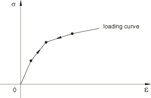
Defining Rate-Independent Elasticity
When the loading response is rate independent, the unloading response is also rate
independent and occurs along the same user-specified loading curve as illustrated in
Figure 2. An unloading curve does not need to be specified.
When the elastic response is rate dependent, both the loading and the unloading curves
can be specified. The unloading data can be rate independent or rate dependent and must
be specified in a single table; that is, only a single unloading data definition is
allowed. If the unloading data are not specified, the unloading occurs along the loading
curve specified with the smallest rate of deformation.
Unphysical jumps in the stress due to sudden changes in the rate of deformation are
prevented using a technique based on viscoplastic regularization. This technique also
helps model relaxation effects in a very simplistic manner, with the relaxation time
given as where , , and are material parameters and is the stretch. is a linear viscosity parameter that controls the relaxation time when . Small values of this parameter should be used; a suggested value is
0.0001s. is a nonlinear viscosity parameter that controls the relaxation time
at higher values of . The smaller this value, the shorter the relaxation time. The
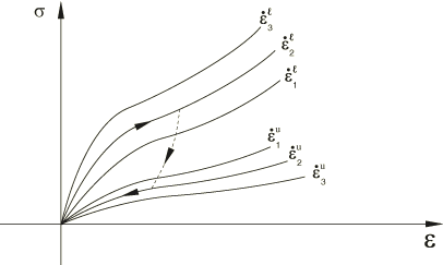
suggested value for this parameter is 0.005s. controls the sensitivity of the relaxation speed to the fabric strain
component. Figure 3 illustrates the loading/unloading behavior as the component is loaded at a rate and then unloaded at a rate .
Figure 3. Rate-dependent loading/unloading.
The unloading path is determined by interpolating the specified unloading curves. The
unloading need not be rate dependent, even though the loading response is rate
dependent. When the unloading is rate dependent, the unloading path at any given
component strain and strain rate is determined by interpolating the specified unloading
curves.
Input File Usage
Use the following options when the unloading is also rate dependent:
The damage models dissipate energy upon unloading, and there is no permanent deformation
upon complete unloading. You can specify the onset of damage by defining the strain above
which the material response in unloading does not retrace the loading curve.
The unloading behavior controls the amount of energy dissipated by damage mechanisms and
can be specified in one of the following ways:
an analytical unloading curve (exponential/quadratic);
an unloading curve interpolated from multiple user-specified unloading curves; or
unloading along a transition unloading curve (constant slope specified by user) to
the user-specified unloading curve (combined unloading).
Input File Usage
Use the following options to define damage with quadratic unloading behavior:
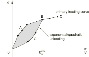
The damage model in Figure 4 is based on an analytical unloading curve that is derived from an energy dissipation
factor, (fraction of energy that is dissipated at any strain level). As the
fabric component is loaded, the stress follows the path given by the loading curve. If
the fabric component is unloaded (for example, at point B), the
stress follows the unloading curve . Reloading after unloading follows the unloading curve until the loading is such that the strain becomes greater than , after which the loading path follows the loading curve. The arrows
shown in Figure 4 illustrate the loading/unloading paths of this model.
Figure 4. Exponential/quadratic unloading.
The unloading response follows the loading curve when the calculated unloading curve
lies above the loading curve to prevent energy generation and follows a zero stress
response when the unloading curve yields a negative response. In such cases the
dissipated energy will be less than the value specified by the energy dissipation
factor.
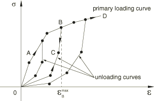
Specifying Interpolated Curve Unloading
The damage model in Figure 5 illustrates an interpolated unloading response based on multiple unloading curves
that intersect the primary loading curve at increasing values of stress/strains. You can
specify as many unloading curves as are necessary to define the unloading response. Each
unloading curve always starts at point O, the point of zero stress
and zero strains, since the damage models do not allow any permanent deformation. The
unloading curves are stored in normalized form so that they intersect the loading curve
at a unit stress for a unit strain, and the interpolation occurs between these
normalized curves. If unloading occurs from a maximum strain for which an unloading
curve is not specified, the unloading is interpolated from neighboring unloading curves.
As the fabric component is loaded, the stress follows the path given by the loading
curve. If the fabric is unloaded (for example, at point B), the
stress follows the unloading curve . Reloading after unloading follows the unloading path until the loading is such that the strain becomes greater than , after which the loading path follows the loading curve.
Figure 5. Interpolated curve unloading.
The unloading curve also has the same temperature and field variable dependencies as
the loading curve.
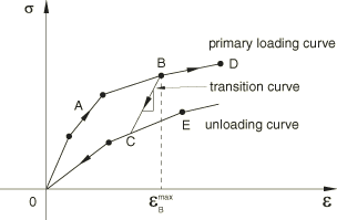
Specifying Combined Unloading
As illustrated in Figure 6, you can specify an unloading curve in addition to the loading curve as well as a constant transition slope that connects the loading curve
to the unloading curve. As the fabric is loaded, the stress follows the path given by
the loading curve. If the fabric is unloaded (for example at point
B) the stress follows the unloading curve . The path is defined by the constant transition slope, and lies on the specified unloading curve. Reloading after unloading
follows the unloading path until the loading is such that the strain becomes greater than , after which the loading path follows the loading curve.
Figure 6. Combined unloading.
The unloading curve also has the same temperature and field variable dependencies as
the loading curve.
Defining Models with Permanent Deformation
These models dissipate energy upon unloading and exhibit permanent deformation upon
complete unloading. You can specify the onset of permanent deformation by defining the
strain below which unloading occurs along the loading curve.
The unloading behavior controls the amount of energy dissipated as well as the amount of
permanent deformation. The unloading behavior can be specified in one of the following
ways:
an analytical unloading curve (exponential/quadratic);
an unloading curve interpolated from multiple user-specified unloading curves; or
an unloading curve obtained by shifting the user-specified unloading curve to the
point of unloading.
Input File Usage
Use the following options to define permanent deformation with quadratic unloading
behavior:
By default, the onset of yield will be obtained as soon as the slope of the loading
curve decreases by 10% from the maximum slope recorded up to that point while traversing
along the loading curve. To override the default method of determining the onset of
yield, you can specify either a value for the decrease in slope of the loading curve
other than the default value of 10% (slope drop = 0.1) or by defining the strain below
which unloading occurs along the loading curve. If a slope drop is specified, the onset
of yield will be obtained as soon as the slope of the loading curve decreases by the
specified factor from the maximum slope recorded up to that point.
Input File Usage
Use the following options to specify the onset of yield by defining the strain
below which unloading occurs along the loading curve:
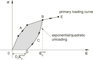
The model in Figure 7 illustrates an analytical unloading curve that is derived from an energy dissipation
factor, (fraction of energy that is dissipated at any strain level), and a
permanent deformation factor, . As the fabric component is loaded, the fabric stress follows the path
given by the loading curve. If the component is unloaded (for example, at point
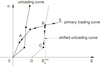
B), the stress follows the unloading curve . The point D corresponds to the permanent
deformation, . Reloading after unloading follows the unloading curve until the loading is such that the strain becomes greater than , after which the loading path follows the loading curve. The arrows
shown in Figure 7 illustrate the loading/unloading paths of this model.
Figure 7. Exponential/quadratic unloading.
The unloading response follows the loading curve when the calculated unloading curve
lies above the loading curve to prevent energy generation and follows a zero stress
response when the unloading curve yields a negative response. In such cases the
dissipated energy will be less than the value specified by the energy dissipation
factor.
Specifying Interpolated Curve Unloading
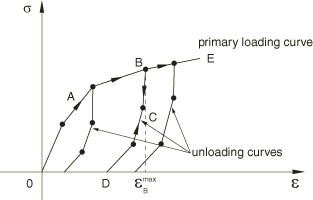
The model in Figure 8 illustrates an interpolated unloading response based on multiple unloading curves
that intersect the primary loading curve at increasing values of stresses/strains.
Figure 8. Interpolated curve unloading.
You can specify as many unloading curves as are necessary to define the unloading
response. The first point of each unloading curve defines the permanent deformation if
the fabric component is completely unloaded. The unloading curves are stored in
normalized form so that they intersect the loading curve at a unit stress for a unit
strain, and the interpolation occurs between these normalized curves. If unloading
occurs from a maximum strain for which an unloading curve is not specified, the
unloading is interpolated from neighboring unloading curves. As the fabric is loaded,
the stress follows the path given by the loading curve. If the fabric is unloaded (for
example, at point B), the stress follows the unloading curve . Reloading after unloading follows the unloading path until the loading is such that the strain becomes greater than , after which the loading path follows the loading curve.
The unloading curve also has the same temperature and field variable dependencies as
the loading curve.
Specifying Shifted Curve Unloading
You can specify an unloading curve passing through the origin in addition to the
loading curve. The actual unloading curve is obtained by horizontally shifting the
user-specified unloading curve to pass through the point of unloading as shown in Figure 9. The permanent deformation upon complete unloading is the horizontal shift applied to
the unloading curve.
Figure 9. Shifted curve unloading.
The unloading curve also has the same temperature and field variable dependencies as
the loading curve.
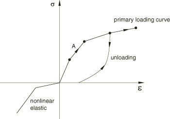
Using Different Uniaxial Models in Tension and Compression
When appropriate, different uniaxial behavior models can be used in tension and
compression. For example, response under tension can be plastic with exponential
unloading, while the response in compression can be nonlinear elastic (see Figure 10).
Figure 10. Different uniaxial models in tension and compression.
User-Defined Fabric Materials
The mechanical response of a fabric material depends on a number of micro and meso-scale
parameters covering the fabric construction and that of the individual yarns as a bundle of
fibers. Often a multiscale model becomes necessary to track the state of the fabric and its
response to loading. Abaqus provides a specialized user subroutine, VFABRIC, to capture the complex
fabric response given the deformed yarn directions and the strains along these directions.
The density (Density) is required when using a fabric
material.
Input File Usage
Use the following options to define a fabric material through user subroutine VFABRIC:
Any material constants that are needed in user subroutine VFABRIC must be specified as part
of a user-defined fabric material definition. Abaqus can be used to compute the isotropic thermal expansion response under thermal loading,
even as the remaining mechanical response is defined by the user subroutine.
Alternatively, you can include the thermal expansion within the definition of the
mechanical response in user subroutine VFABRIC.
Input File Usage
Use the following option to define properties for a user-defined fabric material
behavior:
Many mechanical constitutive models require the storage of solution-dependent state
variables (plastic strains, “back stress,” saturation values, etc. in rate constitutive
forms or historical data for theories written in integral form). You should allocate
storage for these variables in the associated material definition (see Allocating Space for Solution-Dependent State Variables). There is no restriction on the number of state variables
associated with a user-defined fabric material.
State variables associated with VFABRIC can be output to the
output database (.odb) file and results (.fil)
file using output identifiers SDV and
SDVn (see
Abaqus/Explicit Output Variable Identifiers).
User subroutine VFABRIC is called for blocks of
material points at each increment. When the subroutine is called, it is provided with the
state at the start of the increment (fabric stress in the local system, solution-dependent
state variables). It is also provided with the nominal fabric strains at the end of the
increment and the incremental nominal fabric strains over the increment, both in the local
system. The VFABRIC user material interface
passes a block of material points to the subroutine on each call, which allows
vectorization of the material subroutine.
The temperature is provided to user subroutine VFABRIC at the start and the end
of the increment. The temperature is passed in as information only and cannot be modified,
even in a fully coupled thermal-stress analysis. However, if the inelastic heat fraction
is defined in conjunction with the specific heat and conductivity in a fully coupled
thermal-stress analysis, the heat flux due to inelastic energy dissipation is calculated
automatically. If user subroutine VFABRIC is used to define an
adiabatic material behavior (conversion of plastic work to heat) in an explicit dynamic
procedure, the temperatures must be stored and integrated as user-defined state variables.
Most often the temperatures are provided by specifying initial conditions (Initial Conditions) and are
constant throughout the analysis.
Deleting Elements from an Abaqus/Explicit Mesh Using State Variables
Element deletion in a mesh can be controlled during the course of an Abaqus/Explicit analysis through user subroutine VFABRIC. Deleted elements have
no ability to carry stresses and, therefore, have no contribution to the stiffness of
the model. You specify the state variable number controlling the element deletion flag.
For example, specifying a state variable number of 4 indicates that the fourth state
variable is the deletion flag in VFABRIC. The deletion state
variable should be set to a value of one or zero in VFABRIC. A value of one
indicates that the material point is active, while a value of zero indicates that Abaqus/Explicit should delete the material point from the model by setting the stresses to zero. The
structure of the block of material points passed to user subroutine VFABRIC remains unchanged during
the analysis; deleted material points are not removed from the block. Abaqus/Explicit passes zero stresses and strain increments for all deleted material points. Once a
material point is flagged as deleted, it cannot be reactivated. An element is deleted
from a mesh based on the material point status (active or deleted). Details for element
deletion driven by material failure are described in Material Failure and Element Deletion. The status of a material point and an element can be determined by
requesting output variables STATUSMP
and STATUS, respectively.
You can define isotropic thermal expansion to specify the same coefficient of thermal
expansion for the membrane and thickness-direction behaviors.
The membrane thermal strains, , are obtained as explained in Thermal Expansion.
The elastic stretch in a given direction, , relates the total stretch, , and the thermal stretch, :
is given by
where is the linear thermal expansion strain in that direction.
Fabric Thickness
The thickness of a fabric is difficult to measure experimentally. Fortunately, an accurate
value for thickness is not always required due to the fact that a nominal stress measure,
defined as force per unit area in the reference configuration, is used to characterize the
in-plane response. An initial thickness can be specified on the section definition. Accurate
tracking of the thickness with deformation is necessary only if the material is used with
shell elements and the bending response needs to be captured accurately. You can compute the
thickness direction strain increment when the fabric is defined through user subroutine
VFABRIC. For test data–based fabric
materials the thickness is assumed to remain constant with deformation. For a test
data–based fabric definition, you must use the thickness value specified on the section
definition for converting the experimental load data (which are typically available as force
applied per unit width of the fabric) to stress quantities.
Defining a Reference Mesh (Initial Metric)
Abaqus/Explicit allows the specification of a reference mesh (initial metric) for fabrics modeled with
membrane elements. For example, this is useful in airbag simulations to model wrinkles and
changes in yarn orientations that arise from the airbag folding process. A flat mesh may be
suitable for the unstressed reference configuration, but the initial state may require a
corresponding folded mesh defining the folded state. The angular orientation of the yarn in
the reference configuration is updated to obtain the new orientation in the initial
configuration.
Input File Usage
Use the following option to define the reference configuration giving the element
number and its nodal coordinates in the reference configuration:
Defining a reference configuration that is different from the initial configuration
generally results in nonzero stresses and strains in the initial configuration based on
the material definition. By default, compressive initial strains in the yarn directions
generate zero stresses. The stress remains zero as the strain is continuously recovered
from the initial compressive values toward the strain-free state. Once the initial slack
is recovered, any subsequent compressive/tensile strains generate stresses as per the
material definition.
Input File Usage
Use the following option to specify that initial compressive strains are recovered
stress free (default):
Defining Yarn Directions in the Reference Configuration
In general, the yarn directions may not be orthogonal to each other in the reference
configuration. You can specify these local directions with respect to the in-plane axes of
an orthogonal orientation system at a material point. Both the local directions and the
orthogonal system are defined together as a single orientation definition. See Orientations for more
information.
If the local directions are not specified, these directions are assumed to match the
in-plane axes of the orthogonal system defined. The local direction may not remain
orthogonal with deformation. Abaqus updates the local directions with deformation and computes the nominal strains along
these directions and the angle between them (fabric shear strain). The constitutive behavior
for the fabric defines the nominal stresses in the local system in terms of the fabric
strain.
Local yarn directions can be output to the output database as described in Output below.
Picture-Frame Shear Fabric Test
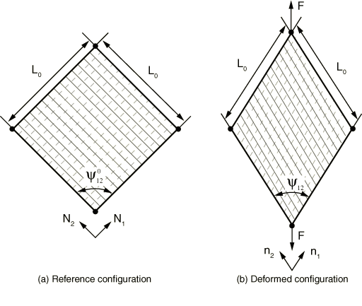
The shear response of the fabric is typically studied using a picture-frame shear test.
The reference and the deformed configuration for a picture-frame shear test under force is illustrated in Figure 11, where is the size of the picture-frame, and is the initial angle between the yarn directions. The four sides of the
specimen are constrained not to change in their length even as the frame elongates and the
angle between the yarn directions decreases with deformation.
Figure 11. Picture-frame shear test on a fabric.
The relationship between the nominal shear stress, , and the applied force, , is
where is the initial volume of the specimen. The fabric engineering shear
strain, , is related to the change in the angle between the yarn directions as
Material Options
The fabric material model can be used by itself, or it can be combined with isotropic
thermal expansion to introduce thermal volume changes (Thermal Expansion). See Combining Material Behaviors for more
details. Thermal expansion can alternatively be an integral part of the constitutive model
implemented in VFABRIC for user-defined fabric
materials.
For a test-data based fabric material, both the mass proportional and the stiffness
proportional damping can be specified (see Material Damping). If
stiffness proportional damping is specified, Abaqus calculates the damping stress based on the current elastic stiffness of the material and
the resulting damping stress is included in the reported stress output at the integration
points.
For a fabric material defined by user subroutine VFABRIC, mass proportional damping
can be specified, but stiffness proportional damping must be defined within the user
subroutine.
Elements
The fabric material model can be used with plane stress elements (plane stress solid
elements, finite-strain shells, and membranes). It is recommended that the fabric material
model be used with fully integrated or triangular membrane elements. When the fabric
material model is used with shell elements, Abaqus does not compute a transverse shear stiffness by default. You must either specify the
material transverse shear modulus (see Defining the Elastic Transverse Shear Modulus) based on which Abaqus can calculate the transverse shear stiffness or define the transverse shear stiffness for
the section directly (see Transverse Shear Stiffness and Defining the Transverse Shear Stiffness).
In addition to the standard output identifiers available in Abaqus (Abaqus/Explicit Output Variable Identifiers), the following
variables have special meaning for the fabric material models:
EFABRIC
Nominal fabric strain with components similar to that of
LE, but with the direct components
measuring the nominal strain along the yarn directions and the engineering shear
component measuring the change in angle between the two yarn directions.
SFABRIC
Nominal fabric stress with components similar to that of the regular Cauchy stress,
S, but with the direct components
measuring the nominal stress along the yarn directions and the shear component
measuring response to the change in angle between the two yarn directions.
By default, Abaqus outputs local material directions whenever element field output is requested to the
output database for fabric models. The local directions are output as field variables
(LOCALDIR1 and
LOCALDIR2) representing the yarn direction
cosines with respect to the orthogonal system at the material point
resulting from the current orientation definition; these variables can be visualized as
vector plots in the Visualization module of Abaqus/CAE (Abaqus/Viewer).
Output of local material directions is suppressed if no element field output is requested
or if you specify not to have element material directions written to the output database
(see Specifying the Directions for Element Output).