Defining the Behavior of a Beam Section Integrated during the Analysis
Use a beam section integrated during the analysis to define the section behavior when numerical integration over the section is required as the beam deforms. You can choose a section shape from the library of beam section shapes provided (see Beam Cross-Section Library) and define the section's dimensions. In addition, you can specify the number of section points to use for integration. The default number of section points is adequate for monotonic loading that causes plasticity. If reversed plasticity occurs, more section points are required.
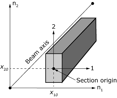
You can also specify an offset for the section origin, as illustrated in Figure 1, for a rectangular cross-section. In Figure 1, the original cross-section axes - are always placed at the beam axis, while the local 1-2 system defines the shifted cross-section axes after offsets of and are applied in the - and -directions, respectively.

Use a material definition (Material Data Definition) to define the material properties of the section, and associate these properties with the section definition. Linear or nonlinear material behavior can be associated with the section definition. However, if the material response is linear, the more economic approach is to use a general beam section (see Using a General Beam Section to Define the Section Behavior).
You must associate the section properties with a region of your model.
Input File Usage
BEAM SECTION, ELSET=name, SECTION=library_section, MATERIAL=name
The ELSET parameter is used to associate the section properties with a set of beam elements.
Include the following option in conjunction with the BEAM SECTION option to specify an offset for the section origin:
BEAM SECTION OFFSET
Abaqus/CAE Usage
Property module: Create Profile: Name: library_section Create Section: select Beam as the section Category and Beam as the section Type, Section integration: During analysis, Profile name: library_section, Material name: name, Offset for origin of cross-section: specify X1 and X2 values : select regions