In the physical construction of most connectors, the admissible
position of one body relative to the other is limited by a certain range. In Abaqus these limits are modeled as built-in inequality constraints. You specify the available
components of relative motion for which the connector stops are to be defined and the lower
and upper limit values of the connector's admissible range of positions in the directions of
the components of relative motion.
Example
Since the shock in Figure 1 has finite length, contact with the ends of the shock determines the upper and lower
limit values of the distance that node b can be from node a.
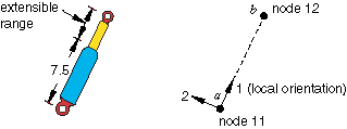
Assume that the maximum length of the shock is 15.0 units and
that the minimum length is 7.5 units. Modify the input file presented in About Connectors that is associated
with the example in Figure 1 to include the following lines:
Connector mechanisms might have devices designed to lock the
connector in place once a desired configuration is achieved. For example, a revolute
connection might have a falling-pin mechanism that locks the rotational motion after
achieving a desired angle. A user-defined connector locking criterion can be defined for
connector elements that contain available components of relative motion. You can select the
component of relative motion for which the locking criterion is defined.
Connector locks can be used to specify connector behavior for
constrained as well as available components of relative motion. Limit values for force or
moment can be specified for all components of relative motion involved in the connection.
The force/moment used in evaluating the criterion is as computed in the output variable CTF. In addition, limit values can be
specified for relative position corresponding to the available components of relative
motion. If no other behavior is specified for an available component of relative motion, a
force locking criterion will not be useful because CTF is zero.
In Abaqus/Explicit you can also specify the limiting values of velocity in the available components as a
criterion for locking. Velocity-dependent locking criteria are useful in modeling seatbelt
systems in automobiles (see Seat belt analysis of a simplified crash dummy). Moreover, the
limiting values can be dependent on temperature and field variables. Field variable
dependencies can be used to model time-dependent locks.
If the locking criterion specified for the selected component of
relative motion is met, either all components lock or a single available component locks in
place. By default, all components of relative motion are locked in place upon meeting the
locking criterion. In this case the connector element will be completely kinematically
locked from that point on. In dynamic analyses this locking may introduce high
accelerations. You can specify if only a selected component of relative motion is locked.
Example
In the example in Figure 1 assume that relative rotations about the shock will lock if the force in the local
3-direction exceeds 500.0 units of force.
Defining Connector Stops and Locks in Linear Perturbation
Procedures
The status of connector locks or stops cannot change during a
linear perturbation analysis; all connector stop and connector lock definitions remain in
the same status as in the base state.
Limitations
Activating a connector stop in a large-displacement analysis can
require relatively small time increments so that the deformation history is continuous in
the vicinity of the value of the relative motion at which you activated the stop. Large time
increments can lead to a discontinuous deformation response that violates the connector
stop.
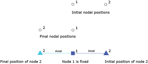
An example of such a behavior is illustrated in Figure 2 in the context of a
simple axial connector that is fixed at one end (node 1) and has an applied compressive load
at the other end (node 2). Assume a specified connector stop behavior that is activated when
the distance between the two nodes is half its initial value. If the compressive load is
large enough and applied in a single increment, the displacement of node 2 can be so large
that it ends up on the opposite side of node 1 (as shown in Figure 2), thereby violating
the connector stop. Using smaller time increments would lead to a more continuous response
that respects the specified connector stop behavior.
At a given time and for a particular component of relative motion
i, the output variable CSLSTi is 1 if the connector is actually
stopped or locked in that component (stop or lock criteria are met). In that case, the
correspondent CRF output variable
will most likely be nonzero and equal to the actual force/moment required to enforce the
stop or lock constraint. Since CRF
is included in the calculation of CTF, the latter will change as well when the lock or stop is active.
If the stop or lock criteria are not met at a given time for a particular component
i, the output variable
CSLSTi is 0 and
in most cases the correspondent reaction force
CRF is zero (the only possible exception
is when a connector motion is also applied in that component).