Surface-based submodeling is provided as a complement to the node-based technique, enabling
you to drive the submodel with stresses from the global model.
Load module: Create Load: choose Mechanical for the Category and Submodel for the Types for Selected Step: Driving region: Specify
Element Types Supported
The following types of submodeling are provided for the surface-based approach
(global-to-submodel):
Two-dimensional models: Solid-to-solid
Three-dimensional models: Solid-to-solid
You can use different element types in the submodel than those used to model the
corresponding region in the global model. In general, for surface-based submodeling Abaqus/Standard supports all continuum elements supported for the static analysis procedure; however,
it does not support the following:
Cylindrical elements
Continuum shell elements
Continuum solid elements with composite sections
Procedures Supported
You can use the surface-based technique only for static analysis in Abaqus/Standard.
Your submodel cannot refer to a global model step that includes multiple load cases (see
Multiple Linear Load Case Analysis). You must perform the global analysis with a
single load definition for the step that will drive the submodel.
Performing a Surface-Based Submodeling Analysis
Your submodel analysis is driven, either partly or completely, from the results obtained
from a global model analysis. The results from the global model are interpolated onto the
surfaces on the appropriate parts of the boundary of the submodel. Thus, the response at the
boundary of the local region is defined by the solution for the global model. The driven
surfaces and any loads applied to the local region determine the solution in the submodel.
Surface-based submodeling should be used only when the node-based technique cannot provide
adequate results. For a comparison of the two submodeling techniques and recommendations for
their application, refer to About Submodeling.
Saving the Results from the Global Model
The results from the global analysis must be saved at all elements required for the
interpolation of the driven variables to the boundary surface of the submodel. Only the
output database (in ODB or
SIM format) can be used for this purpose.
In each step of the global model whose solution will be used to drive the submodel, write
the stress results to the output database (see Output to the Output Database).
Referring to the Global Model Results from the Submodel Analysis
You must define the source of the global solution results and provide the name of the
output database file (in ODB or
SIM format); the file extension is optional. If the
file extension is omitted, Abaqus will use in order, the ODB output database file or the
SIM database file.
Input File Usage
abaqusjob=submodel_input_fileglobalmodel=
global_output_database or
sim_database_file
Abaqus/CAE Usage
Any module: ModelEdit Attributessubmodel: Submodel: Read data from job: global_output_database
Reading data from a SIM database file is not
supported in Abaqus/CAE.
Specifying the Global Elements Used to Drive the Submodel
Specifying the driven element-based surfaces does not activate the driven surface loads:
they must be activated by specifying the appropriate submodel distributed surface loads.
All surface facets of the submodel to be driven by stresses in any step must be specified
as driven surfaces since the list of surfaces cannot be extended subsequent to its initial
definition (even at restart). However, variables at the surfaces given do not have to be
driven in all steps: the choice of which surfaces are driven in a particular step is made as
part of a submodel distributed surface load definition, as discussed in Defining the Driven Surface Tractions in the Submodel later in this
section.
The SUBMODEL option must be included
in the model definition portion of the input file for the submodel analysis. Multiple
SUBMODEL options are allowed;
however, in this case you must ensure that the driven surfaces specified on the data line
of one option are separate and distinct from the other surfaces specified on the data
lines of all the other options.
Abaqus/CAE Usage
Load module: Create Load: choose Other for the Category and Submodel for the Types for Selected Step: Driving region: select region
Defining Geometric Tolerances
A geometric tolerance is used to define how far driven element-based surface nodes in the
submodel can lie outside the exterior surface of the global model, as that surface is
interpolated in the global, undeformed finite element model. By default, surface nodes in
the submodel must lie within a distance calculated by multiplying the average element size
in the global model by 0.05. You can change the tolerance, which is useful in cases where
submodel driven surfaces lie to a greater extent outside the global model exterior
surface. Tolerances larger than this default value, however, can result in significantly
greater computation times and lower accuracy in the driven solution for driven surface
regions significantly outside the global model exterior surface.
You can define the geometric tolerance as a fraction of the size of the average element
in the global model or as an absolute distance in the length units chosen for the model.
If both tolerances are defined, Abaqus uses the tighter tolerance.
Input File Usage
Use the following option to define the geometric tolerance as an absolute
distance:
Load module: Create Load choose Other for the Category and Submodel for the Types for Selected Step: select region: Exterior tolerance: absolute: or relative:tolerance
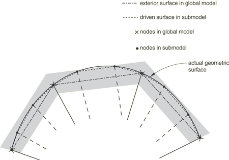
The Exterior Tolerance in Solid-to-Solid Submodeling
The exterior tolerance for a solid-to-solid submodel analysis is indicated by the
shaded region in Figure 2. If the distance between the driven surface nodes and the free surface of the global
model falls within the specified tolerance, the solution variables from the global model
are extrapolated to the submodel.
Figure 2. The exterior tolerance in surface-based submodeling.
Defining the Driven Surface Tractions in the Submodel
The actual driven surface tractions are defined in any step as submodel distributed surface
loads. The stresses resulting in these tractions are “driven variables” obtained from the
output database file of the global analysis.
All stress components from the global model elements that will drive the submodel boundary
surface must have been written to the output database. They will be used to create traction,
shear, and normal stresses at integration points of driven surfaces (as nonuniform
distributed surface loads). All applicable stress components are calculated and applied to
the surface integration points at each time increment.
Load module: Create load: choose Other for the Category and Submodel for the Types for Selected Step: select region: Global step number:step
Modifying the Set of Driven Surface Tractions
You can modify the submodel distributed surface load definitions from step to step to
change the global step reference, you can remove surface load definitions, and you can
reintroduce them later (see About Loads). Submodel
distributed surface loads do not propagate between steps. At each new step all submodel
distributed surface loads defined in previous steps will be removed unless they are
modified or redefined. New surfaces cannot be added to the total set of driven surface
defined for the submodel; this set of driven surfaces is a fixed part of the model
definition.
Guidelines for Obtaining Adequate Solution Accuracy
Unlike node-based submodeling, surface-based submodeling can in many cases provide
incorrect or misleading submodel results. This risk follows from the methods used to
interpolate stresses from the global model to the submodel:
The global model material point stresses are smoothed and associated with the global
model nodes.
These global model node-located stresses are then interpolated to the submodel surface
integration points and applied as tractions.
This process is generally nonconservative, resulting in a submodel traction field that is
not equivalent to the global model stress field in an equilibrium sense.
Modeling Guidelines
You can improve accuracy and achieve reasonable submodel solutions by observing the
following guidelines:
Design your models so that your submodel surface intersects the global model in
regions of relatively low stress gradients.
Design your models so that your submodel surface intersects the global model in
regions of uniform element size. A warning message is provided in the data
(.dat) file in cases where significant nonuniform element size
distributions are seen.
Checking Your Results
To understand whether your modeling approach results in a reasonably accurate solution,
the following guidelines are recommended:
Compare the stress distributions on the submodel-driven surfaces with the stress
distributions in the global model. You can view the stress
distributions in the global model by using tools such as cutting planes and path
plots in the Visualization module of
Abaqus/CAE. The degree to which the global model's stress distributions agree with
those in the submodel-driven surface is generally an indication of the level of
accuracy of your submodel solution.
When using inertia relief in the submodel for cases where submodeling does not remove
all rigid body modes, compare the inertia relief forces to the prevailing force level
in your submodel. If the inertia relief force is large compared to the prevailing
force level, your submodel results might be inaccurate.
Special Considerations
There are several special considerations that are worth noting.
Handling of Rigid-Body Modes
When you use surface-based submodeling exclusively to drive your submodel response, your
displacement solution will not be unique; you will generally encounter rigid-body modes
and accompanying numerical issues. You can address these rigid-body modes by
providing sufficient node-based submodel displacement boundary condition definitions
in the submodel analysis,
providing sufficient boundary condition definitions in the submodel analysis, or
providing an inertia relief load definition in the submodel analysis (see Inertia Relief).
You can combine these definitions, as necessary and appropriate to your model, to address
all rigid body modes.
Cases of Finite Rotation
Global model stress results are stored in the output database in the global coordinate
system. Submodel tractions are calculated from these stresses and the current
configuration surface normal in the submodel. Hence, when your global model result
involves significant finite rotation, your submodel results will generally be inaccurate
unless you provide sufficient node-based submodel displacement boundary condition
definitions to impart similar rigid-body rotations to the submodel; exclusive use of
surface-based submodeling definitions is not adequate to provide these rigid-body motions.
You might also experience convergence difficulties in the submodel when it is not properly
rotated.
Inelastic Behavior
When surface-based submodeling is used to drive a submodel region with an inelastic
material definition, you might encounter rigid-body modes and accompanying numerical
issues. For example, numerical issues will prevent convergence if the submodel material
definition includes plasticity and the submodel loading results in a shear band formation
beyond the material hardening definition, such that unconstrained motion can occur (that
is, if the submodel loads exceed the limit load capacity). In these cases node-based
submodeling should be used.
Procedures
Only the static procedure is allowed. Both general (possibly nonlinear) and linear
perturbation steps can be used in submodeling (see General and Perturbation Procedures for a discussion of general and linear perturbation
steps).
Obtaining a Solution at a Particular Point in Time Using Linear Perturbation
Analysis
In Abaqus/Standard it is possible to study the submodel's linearized response corresponding to a
particular point in time in the global solution by using a static, linear perturbation
procedure in the submodel analysis. You can select the increment in the global analysis
step that is to be used as the basis for calculating the values for the driven variables.
If you do not select an increment in a static linear perturbation step, the last increment
of the selected step in the global analysis is used as the basis for calculating the
values for the driven variables. You cannot select an increment in a general submodel
step.
Selection of a specific global model increment is not supported in Abaqus/CAE.
Mixing General and Linear Perturbation Steps
It is possible to mix general steps and linear perturbation steps in both the global and
the submodel analyses. Abaqus allows general analysis steps to be treated as linear perturbation steps during
submodeling, and vice versa.
Example: Submodeling with General and Linear Perturbation Steps
For an example of submodeling that uses both general and linear perturbation steps,
consider the following situation. The global analysis consists of a static preload—done
as a general, nonlinear, analysis step—followed by extraction of the eigenmodes of the
preloaded structure, then a step of 5 seconds of modal dynamic response analysis:
STEP
** Apply preload
STATIC
0.1, 1.0
…
** Write out stress results for elements needed to
** interpolate to the submodel's surfaces
ELEMENT OUTPUT, ELSET=DETAILSEND STEPSTEP
** Calculate modes and frequencies
FREQUENCY
…
** The ELEMENT OUTPUT option is repeated because
** this is the first linear perturbation step
ELEMENT OUTPUT, ELSET=DETAILUEND STEPSTEP
** Dynamic response of preloaded system
MODAL DYNAMIC
0.01, 5.0
…
END STEP
We wish to study the local, possibly nonlinear, response of a part of this model that
is so small that we do not need to model dynamic effects locally and can, thus, perform
two steps of static analysis:
** Define submodel surfaces (driven surfaces)
SUBMODEL,TYPE=SURFACE
PERIM
STEP
** Preload
STATIC
0.1, 1.0
DSLOAD, SUBMODEL, STEP=1
…
END STEPSTEP
** Local static response to global dynamic step
STATIC
0.01, 5.0
DSLOAD, SUBMODEL, STEP=3
…
END STEP
It is perfectly acceptable that the submodel analysis requests general, possibly
nonlinear, analysis for both steps, while in the global analysis the dynamic step was a
linear perturbation step (modal dynamics is always a linear perturbation analysis). It
is your responsibility to judge that this use of the submodeling feature is reasonable.
For example, suppose that the global analysis were continued with a fourth step of
general, nonlinear static response:
RESTART, READ, STEP=3
** Read state at end of initial preload
** (could equally well use RESTART, READ, STEP=1)
STEP
** Add more preload
STATIC
 0.2, 1.0
…
END STEP
This fourth general analysis step starts with the state at the end of general analysis
Step 1 because the frequency extraction and the modal dynamic steps are both linear
perturbation steps. However, if we restart the submodel analysis in the same way, the
solution might not be comparable with the global model solution:
RESTART, READ, STEP=2
** Read state at end of step 2
STEP
** Add more preload
STATIC
 0.2, 1.0
DSLOAD, SUBMODEL, STEP=4
…
END STEP
The second step in the submodel is a general analysis step, to which the response might
be nonlinear, thus changing the state of the model. A valid alternative would be to
apply the Step 4 response to the submodel immediately after the first step:
RESTART, READ, STEP=1
** Read state at end of preload step
STEP
** Add more preload
STATIC
 0.2, 1.0
DSLOAD, SUBMODEL, STEP=4
…
END STEP
Loads
Any loads that are applied in the submodel region of the global analysis must be imposed in
the submodel analysis in the usual way. It is your responsibility to apply such loads to the
submodel correctly so that they correspond to the loading of the global model. See About Loads for an overview
of the loads available in Abaqus.
As described above, element stress output requests to the output database file must be used
in the global analysis to save the values of the driven variables at the submodel boundary.
HEADING
…
SUBMODEL,TYPE=SURFACE, EXTERIOR TOLERANCE=toleranceList of all surfaces to be driven
**
STEPSTATIC (or any other allowable procedure)
Data line to define step time and control incrementation.
…DSLOAD, SUBMODEL, STEP=1
Data lines listing surfaces to be driven in this step
…
END STEP