Additional Contact Initialization Options for Small-Sliding Contact in Abaqus/Standard
In Abaqus/Standard you can define precise initial clearance or overclosure values and contact directions for
contact initialization in small-sliding contact for both contact pairs and general contact.
Defining Precise Initial Clearance or Overclosure Values
You can define precise initial clearance or overclosure distances and contact directions
when they would not be computed accurately enough from the surface geometry. You can define
initial clearance or overclosure values only for small-sliding contact (Contact Formulations in Abaqus/Standard) whether contact is modeled with contact pairs or
with general contact. For a technique that can be used to model clearances or overclosures
between finite-sliding contact pairs, see Alternative Methods for Specifying Precise Initial Clearances or Overclosures.
The initial clearance or overclosure value calculated for a potential contact constraint
based on surface geometry is overwritten by the value that you specify. This procedure is
performed internally, and it does not affect nodal positions. If you define positive
clearance, Abaqus/Standard treats the two surfaces as not being in contact, regardless of their nodal coordinates.
If you define an overclosure, Abaqus/Standard treats the two surfaces as an interference fit and attempts to resolve the overclosure in
the first increment. If the defined overclosure is large, you might need to specify an
allowable interference that is ramped off over several increments. See Modeling Contact Interference Fits in Abaqus/Standard for further discussion of interference fits.
Specifying a Uniform Clearance or Overclosure for the Surfaces
You can specify a uniform clearance or overclosure for a contact pair by identifying the
main and secondary surfaces of the contact pair and the desired initial clearance, (positive for a clearance; negative for an overclosure). No other data are
needed.
For general contact, you can specify a named clearance to associate with contact
initialization for portions of the general contact domain where small sliding is active.
Input File Usage
Use the following option to specify a uniform clearance or overclosure for a contact
pair:
Interaction module: contact interaction editor: Clearance: Initial clearance: Uniform value across secondary surface:
Specifying initial clearance or overclosure for small-sliding contact in general
contact is not supported in Abaqus/CAE.
Specifying Spatially Varying Clearances or Overclosures for the Surfaces
Alternatively, you can specify spatially varying clearances or overclosures by providing a
table of data specifying nodal clearance values. You can specify these clearances for nodes
of either surface of a small-sliding contact interaction within general contact; for
small-sliding contact pairs, you must specify these clearances on nodes belonging to the
secondary surface. General contact assigns implicit main-secondary roles by default. If you
specify clearance values on nodes that act as main nodes, Abaqus/Standard interpolates the clearance used for an individual contact constraint from the clearance
values of the main nodes participating in the contact constraint. If user-specified
clearances do not apply to a particular contact constraint, Abaqus/Standard calculates the initial clearance from the initial geometry of the contacting
surfaces.
For general contact, you can create a named clearance to associate with contact
initialization for portions of the general contact domain where small sliding is active. For
contact pairs, identify the main and secondary surfaces along with clearance data.
Input File Usage
Use the following option to specify spatially varying clearances or overclosures for
contact pairs:
CLEARANCE, SECONDARY=surface_name, MAIN=surface_name, TABULARnode number or node set label, clearance value
Repeat the data line as often as necessary.
Use the following options to specify spatially varying clearances or overclosures for
general contact:
CLEARANCE, NAME=clrName, TABULARnode number or node set label, clearance value
The following options assign the surface surf_1 a secondary
role assuming the nodes with specified clearances belong to it before the surface pair
surf_1 and surf_2 are assigned the
named clearance during contact initialization.
You cannot specify initial clearance or overclosure values using an external input
file in Abaqus/CAE.
Specifying the Surface Normal for the Contact Calculations
Normally Abaqus/Standard calculates the surface normal used for the contact calculations from the geometry of
the discretized surfaces, using the algorithms described in Contact Formulations in Abaqus/Standard. When specifying spatially varying clearances or
overclosures, you can redefine the contact direction that Abaqus/Standard uses with each secondary node by specifying the components of this vector. The vector
must be defined in the global Cartesian coordinate system, and it should define the main
surface's desired outward normal direction.
For general contact, instead of specifying the secondary and main roles, the clearance
definition is identified by a name which is then associated with a contact initialization
definition.
Input File Usage
Use the following option to specify the surface normal for the contact calculations
for contact pairs:
CLEARANCE, SECONDARY=surface_name, MAIN=surface_name, TABULARnode number or node set label, clearance value, first normal component, second normal component,third normal component
Repeat the data line as often as necessary.
Use the following options to specify the surface normal for the contact calculations
for general contact:
Generating Contact Normal Directions Based on a Reference Thread Geometry
This modeling approach provides a simple way to approximate effects of threads without
directly including threads in the mesh geometry. The meshed parts typically have cylindrical
surfaces at the interface with this approach, such that default contact normal directions
are approximately radial. This capability adjusts contact normal directions to be normal to
faces of reference threads. The thread face normal directions have large components in the
radial and axial directions and (for three-dimensional models only) a small component in the
circumferential direction due to the spiral nature of the threads. Either the bolt or bolt
hole can act as the secondary surface.
The capability to adjust contact normal directions based on reference thread geometry is
available only for small-sliding contact formulations, so it will not provide accurate
results after relative twisting motion between a bolt and hole. For simulations involving
relative twisting motion, you can consider the following alternative modeling approach:
Create nominal meshes without threads for the
bolts and parts with bolt holes.
Create surface element meshes to capture the
bolt thread geometry and bolt hole thread geometry.
Specify surface-based tie constraints to
constrain each bolt thread surface to a bolt and each hole thread surface to a hole.
Specify finite-sliding contact (with penalty
enforcement of contact constraints) between the respective thread surfaces.
Uniform Association with Top or Bottom Thread Face
By default with the capability based on reference thread geometry, all secondary nodes
are assumed to consistently correspond to the "top" or "bottom" thread face, such that
adjusted contact normal directions for all secondary nodes have the same axial component
and the same (small) circumferential component. In this case, the overall contact
interface provides only "one-way" resistance to relative axial motion between the bolt and
bolt hole.
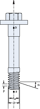
You specify the thread geometry parameters along with two points "a" and "b," as shown in
Figure 1, defining the axis of the bolt/bolt hole. The contact
interface supports tension in a bolt if point "a" is near the bolt tip and point "b" is
near the bolt head (as in Figure 1), and it supports compression in the bolt if points "a" and
"b" have the opposite orientation. If a negative half-thread angle is specified, the
opposite convention for supporting tension or compression occurs.
For general contact, instead of specifying the secondary and main roles, the clearance
definition is identified by a name label to be associated with a contact initialization
definition (as in earlier cases). Nodes specified for the applicable region of the
reference thread geometry can correspond to nodes of either surface of small-sliding
contact interactions.
Figure 1. Reference thread geometry.
Input File Usage
Use the following option to specify a uniform association with the top or bottom
thread face for contact pairs:
CLEARANCE, SECONDARY=surface_name, MAIN=surface_name, TABULAR, BOLT,
NORMAL ADJUSTMENT=UNIFORM AXIAL COMPONENThalf-thread angle, pitch, major bolt diameter, mean bolt diameternode number or node set label, clearance value, coordinates of points a and b on the axis of the bolt/bolt hole
Repeat the second data line as often as necessary.
Use the following options to specify a uniform association with the top or bottom
thread face for general contact:
CLEARANCE, NAME=clrName, TABULAR, BOLT, NORMAL ADJUSTMENT=UNIFORM AXIAL COMPONENThalf-thread angle, pitch, major bolt diameter, mean bolt diameternode number or node set label, clearance value, coordinates of points a and b on the axis of the bolt/bolt hole
Repeat the second data line as often as necessary.
Interaction module: contact interaction editor: Clearance: Initial clearance:Computed for single-threaded bolt or Specify for single-threaded bolt:clearance value,
Secondary node set for clearance:Edit Region: select region,
Bolt direction vector:Edit: select axis,
Half-thread angle:half-thread angle, Pitch:pitch,
Bolt diameter:Major:major bolt diameter or Mean:mean bolt diameterNormal adjustment:Uniform
Specifying initial clearance and/or contact directions for contact initialization
for general contact is not supported in Abaqus/CAE.
Location-Dependent Association with Top or Bottom Thread Face
Optionally, each secondary node can be associated with the top or bottom thread face
based on its initial position with respect to the reference thread geometry, which will
influence the sign of the axial and circumferential components of the adjusted contact
normal direction for each secondary node. Having some secondary nodes associated with the
top thread face and others associated with the bottom thread face restricts motion of the
bolt with respect to the hole in both axial directions and supports tension or compression
in the bolt. It is unlikely that all secondary nodes will be associated with the same (top
or bottom) thread face with this non-default option. For example, consider that a purely
circumferential mesh line would be associated with the top thread face over a 180° arc and
the bottom thread face over the remaining 180° arc.
With this location-dependent association with top and bottom thread faces, contour plots
of contact stress on bolt/hole surfaces often show stripes at intervals corresponding to
the threads in the reference thread geometry.
Input File Usage
Use the following option to specify a location-dependent association with the top or
bottom thread face for contact pairs:
CLEARANCE, BOLT, NORMAL ADJUSTMENT=LOCATION DEPENDENT
Use the following options to specify a location-dependent association with the top
or bottom thread face for general contact:
Interaction module: contact interaction editor: Clearance: Initial clearance:Computed for single-threaded bolt or Specify for single-threaded bolt:clearance value, Normal adjustment:Location dependent
Specifying initial clearance and/or contact directions for contact initialization
for general contact is not supported in Abaqus/CAE.
Right-Handed Versus Left-Handed Reference Thread Geometry
The reference thread geometry corresponds to right-handed threads by default; however,
you can specify left-handed reference thread geometry optionally. Left-handed threads have
the opposite effect on the circumferential component of the contact normal direction as
right-handed threads.
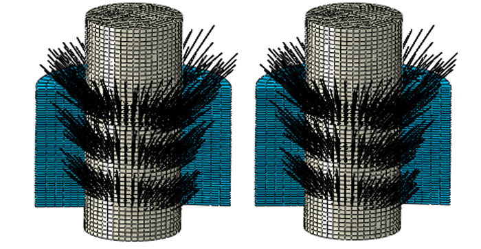
Figure 2
shows that nodal contact force results on a bolt surface are not sensitive to whether
thread geometry information is specified for nodes on one surface or the other for a
small-sliding general contact interaction. In the case shown on the left, thread geometry
information associated with left-handed threads is specified on the bolt (main) surface;
in the case shown on the right, thread geometry information associated with left-handed
threads is specified on the bolt-hole (secondary) surface. Abaqus/Standard internally assigns the bolt surface to act as the main surface for both of these
simulations. For small-sliding contact pairs, you must specify thread geometry information
on the secondary surface. General contact automatically assigns main and secondary roles;
in this example, the bolt acts as the main surface.
Figure 2. Cut-away views of contact force vectors.
Input File Usage
Use the following option to specify that the reference threads are right-handed for
contact pairs:
Interaction module: contact interaction editor: Clearance: Initial clearance:Computed for single-threaded bolt or Specify for single-threaded bolt:clearance value, Handedness:Right or Left
Specifying initial clearance and/or contact directions for contact initialization
for general contact is not supported in Abaqus/CAE.
Visualizing the Precise Initial Clearances or Overclosures
Abaqus/Standard does not adjust the coordinates of the secondary surface when precise initial clearances
or overclosures are specified. Therefore, the specified clearances or overclosures cannot be
seen in the model in Abaqus/CAE. Thus, depending on the initial geometry of the surfaces and the magnitude of the
clearances or overclosures, the surfaces may appear open or closed in Abaqus/CAE when they are actually just in contact. However, the actual clearance can be displayed in
Abaqus/CAE by plotting a contour plot of the variable
COPEN.