Typical Applications
Thermal fluid pipe connector elements are typically used to simulate the junction between two or more thermal fluid pipe elements (see Thermal Fluid Pipe Elements) such as a valve, a T-connector, or a diffuser.
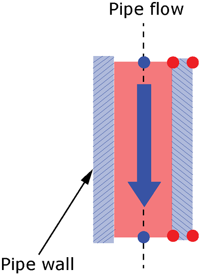
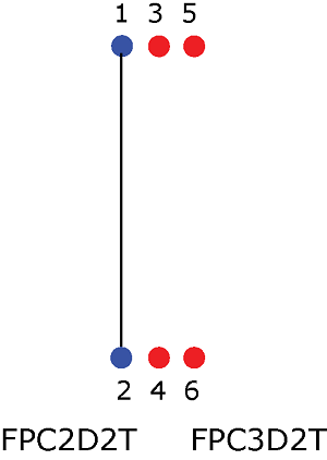
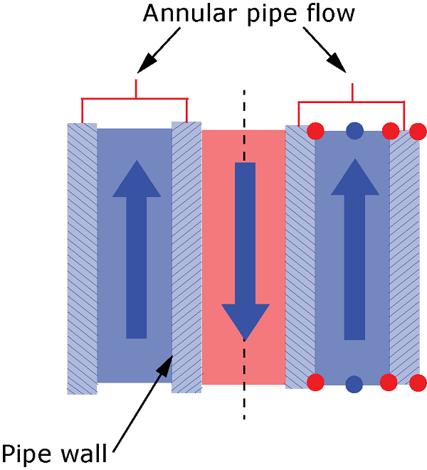
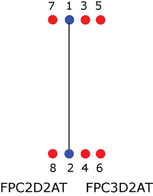
Products Abaqus/Standard Typical ApplicationsThermal fluid pipe connector elements are typically used to simulate the junction between two or more thermal fluid pipe elements (see Thermal Fluid Pipe Elements) such as a valve, a T-connector, or a diffuser. Choosing an Appropriate ElementSeveral thermal fluid pipe connector elements are available. They can be broadly classified as regular thermal fluid pipe connector elements or annular thermal fluid pipe connector elements. Element types FPC2D2T and FPC3D2T belong to the class of regular thermal fluid pipe connector elements. Element types FPC2D2AT and FPC3D2AT belong to the class of annular thermal fluid pipe connector elements that enable the modeling of the annulus region of a connector. For a detailed discussion of the differences between the two classes (regular versus annular) of thermal fluid pipe elements, see Choosing an Appropriate Element in Thermal Fluid Pipe Elements. Similar considerations carry over for the corresponding connector elements. The geometric layout of the regular and annular thermal fluid pipe connector elements and the corresponding element connectivities are shown in the figures below. The nodes at each end are geometrically coincident. Even though the figures show these elements to have finite lengths, the geometric length of the connectors (based on the nodal coordinates of its two ends) is ignored in the pressure drop computations. You can use an offset to create the pipe wall nodes of both the regular and the annular thermal fluid pipe connector elements.     Input File Usage Use the following option to define an offset used to create the connector pipe wall nodes: ELEMENT, OFFSET=number Assigning a Material Definition to a Set of Thermal Fluid Pipe Connector ElementsYou must associate a material definition with each connector element section property. The material that is defined for the thermal fluid pipe connector section refers to the fluid that is flowing through the connector. You must define the following properties for the fluid: fluid density and viscosity. For the viscosity definition, thermal fluid pipe connector elements support both Newtonian and non-Newtonian fluids. The following non-Newtonian fluid models are supported: power law, Bingham Plastic, and Herschel-Bulkley models (see Viscosity). For the thermal fluid pipe connector elements, you must also specify the following thermal properties:
Input File Usage Use the following options to specify the flow and thermal properties of the fluid: FLUID PIPE CONNECTOR SECTION, MATERIAL=material name MATERIAL, NAME=material name VISCOSITY, DEFINITION=NEWTONIAN or POWER LAW or HERSCHEL-BULKLEY or BINGHAM PLASTIC DENSITY, PORE FLUID CONDUCTIVITY, PORE FLUID SPECIFIC HEAT, PORE FLUID In addition, use the following options to specify the thermal properties for the pipe wall connector: DENSITY CONDUCTIVITY SPECIFIC HEAT Multiple Fluid FlowAbaqus allows the use of multiple fluids in an analysis, up to a maximum of four fluid types. This capability is useful in situations where the spatial distribution of the different fluid types is known (that is, precomputed) at all times during the analysis. In other words, the type of fluid at each node in the domain is known at all times during the analysis. The definition of multiple fluids in an analysis involves associating each fluid with a unique integer and a specific predefined field variable. This integer acts as a fluid identifier. You can utilize this fluid identifier to specify the properties (for example, viscosity) of each fluid. The field variable associated with a fluid type allows you to predefine the fluid type at a node as a function of time using amplitude definitions, or as functions of both time and space utilizing user subroutine UFIELD or USDFLD. You specify a value for each field variable, which is associated with a fluid identifier, at each node. It is recommended that you specify a value for the field variable ( ) such that, . Abaqus assigns the fluid type at an integration point to be the one for which the field variable has the maximum value at that point. If all field variables have the same numerical value at an integration point, the first fluid (fluid identifer 1) is assumed to be active. Input File Usage VISCOSITY, FLUID ID=Fluid Id number, DEFINITION=NEWTONIAN or POWER LAW or HERSCHEL-BULKLEY or BINGHAM PLASTIC FLUID ID FIELD Fluid Id number, field_id Thermal Fluid Pipe Connector EquationsThe main governing equations for the fluid flow and pressure loss can be found in Fluid Pipe Connector Equations. The different options of defining discrete pressure loss can be found in Specifying the Fluid Pipe Connector Geometry and Connector Loss. You can also define a control valve behavior in thermal fluid pipe connector elements as described in Specifying the Control Valve Behavior. Specifying the Wall Diameters for Thermal Fluid Pipe Connector ElementsYou must define the geometry of the connector wall as a circular cross-section by specifying the inner and outer wall radii. Input File Usage FLUID PIPE CONNECTOR WALL Specifying the Thermal Loss in the FluidYou can define the thermal loss due to the fluid flow in the thermal fluid pipe connector elements. Input File Usage FLUID PIPE CONNECTOR THERMAL LOSS Specifying Initial and Prescribed ConditionsYou can define an initial temperature or field distribution over the nodes of the thermal fluid pipe connector elements. Input File Usage Use one or both of the following options: INITIAL CONDITIONS, TYPE=TEMPERATURE INITIAL CONDITIONS, TYPE=FIELD Specifying Loads and Boundary ConditionsThermal fluid pipe connector elements allow for the specification of pressure boundary conditions and volumetric flow rates at the nodes. The flow rate must be a nonzero value. At a particular node, you can specify either a pressure or flow rate but not both. Because the thermal fluid pipe connector elements do not use the geometric length in the fluid equilibrium equations, gravity loads are not supported for these elements. You can specify boundary conditions on the temperature degree of freedom. Input File Usage Use the following option to specify the pressure at the inlet or outlet: BOUNDARY node or node set, 8, 8, magnitude Use the following option to specify the flow rate at the inlet or outlet: CFLOW node or node set, , magnitude Use the following option to specify the temperature at the inlet or outlet: BOUNDARY node or node set, 11, 11, magnitude | |||||||||||||||