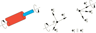
The six components of relative motion, denoted
and
for ,
are defined in the description for each connection, where needed. These
components include constrained and available components of relative motion.
Forces and moments are denoted
and .
These quantities are either constraint forces and moments, which enforce the
kinematic constraints on the constrained components of relative motion, or
kinetic forces and moments, which are the work conjugate variables to the
available components of relative motion. For example, the REVOLUTE connection type has one available component of relative
motion, ,
and two kinematic rotation constraints (equivalent to setting two rotation
components,
and ,
to zero). Conjugate to the available rotation component is the kinetic moment
acting about the local -direction.
In general, kinetic forces and moments include the effects of connector
behaviors, such as elastic springs, viscous damping, friction, and reaction
forces and moments due to connector stops and locks. For constitutive response
defined as a function of displacement or rotation, the initial position may not
correspond with the reference position where constitutive forces and moments
are zero. You can define reference lengths and angles (given in degrees) for
connector behavior as described in
Defining Reference Lengths and Angles for Constitutive Response.
These reference quantities define
and ,
the connector constitutive displacements and rotations. These constitutive
displacements and rotations are used only to define constitutive response and
differ from the relative displacements and rotations measured in the connector
elements only when you define the reference lengths or angles.
As an example, if the REVOLUTE connection included linear spring and dashpot behavior
combined with a connector stop,
where
is the spring stiffness,
is the dashpot coefficient, and
is the reaction moment caused by the connector stop. In the REVOLUTE connection there are two constraint moment components,
about
and
about .
Interpreting Connector Forces and Moments
The kinematic constraint and kinetic forces and moments are always computed as work conjugates
of the kinematics in the connector (components of relative motion). In most connection
types one direct consequence is that the constraint forces (and moments) in connectors are
reported as the forces (and moments) applied at the second node but in the local system
associated with the first node. Since the kinematics are complex in many of the connection
types, the connector forces and moments can be somewhat surprising on first inspection.
For example, consider the case of a
HINGE connection defined with the
local
-direction aligned with the global X-direction and
the local
-direction aligned with the global Y-direction. Assume that the second
connector node is grounded and that the first node is subjected to a concentrated load
along the global Y-direction. If the only available relative rotation
in the HINGE is constrained with a
zero-valued connector motion, the second node does not rotate with respect to the first
node and the connector reaction force along the local
-direction matches the applied load while the other two connector
reaction forces are zero. However, if a nonzero connector motion is specified, the first
connector reaction force is still zero while both the second and third connector reaction
forces are nonzero and only the vector-norm of these two forces matches the applied load.
In both cases the only nonzero nodal reaction force at the second connector node is the
one in the global Y-direction, as dictated by the equilibrium in a
free body diagram. Hence, the connector reaction forces and nodal reaction forces are not
equivalent in most cases.
