SLIPRING | |||||||||
|
| ||||||||
Products Abaqus/Standard Abaqus/Explicit Abaqus/CAE
Description
The SLIPRING connection does not constrain any component of relative motion. Hence, there is no restriction on the position of the connector nodes.
The distance between nodes is
The belt material can flow and stretch between nodes a and b. Flow can occur with no stretching (such as in a rigid belt), stretching can occur with no flow (such as when the flow is constrained at both nodes of the connector), or both flow and stretching can occur simultaneously (such as in compliant belts). By convention, the material flow at node a is positive if it enters segment and is positive at node b if it exits the segment. A reference length can be defined in incremental fashion as
where is the reference length at the end of the current increment, is the reference length at the beginning of the current increment, is the incremental flow at node a, and is the incremental flow at node b. The stretch in the belt can then be defined as
and the “strain” in the belt can be computed as
At the beginning of the analysis, the reference length at is
where is the initial stretch of the belt. By default, the initial stretch is meaning that there are no initial strains in the belt. You can specify initial strains in the belt, , by specifying a connector constitutive reference. The initial stretch is then computed using
The second available component of relative motion is simply the material flow past node b,
The third component of relative motion is the material flow into node a and is used only for output:
The kinetic force is
Limitations
At most two SLIPRING connectors can share a common node. The following limitations apply with respect to the kinetic behavior that can be defined in the SLIPRING connection type:
-
Only predefined friction can be defined in the second component of relative motion as outlined below.
-
In Abaqus/Explicit plasticity, damage and lock connector behavior cannot be specified.
-
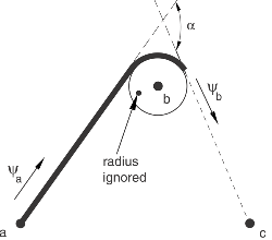
The connectivities of the two adjacent SLIPRING connector elements sharing a common node b (Figure 1) should be in the typical order a–b and b–c. In addition, any two adjacent SLIPRING connector elements must refer to the same connector behavior except for the friction data.
Friction
Predefined Coulomb-like friction in the SLIPRING connection relates the tension in the belt segment (kinetic force in component 1) to the tension in the adjacent belt segment . In the simpler case of frictionless sliding, the two tensions are equal (apart from inertial effects due to the motion of the belt in dynamic analyses). If frictional effects are included as material flows past node b, the two tensions differ by the total friction force (CSF2) over the contact arch between the belt and the ring (angle ).
The Coulomb-like frictional effect is a well-known analytical result. In the case when frictional sliding occurs in the direction illustrated in Figure 1, the tensions in the two segments, and , are related as follows:
where is the friction coefficient. The friction force is simply the difference
More formally, the frictional relationship is modeled by considering the potential function
Frictional stick occurs if ; and sliding occurs if , in which case the tension force = . Friction forces do not develop if the kinetic force is compressive. When sliding occurs in the opposite direction, the sign of the exponent in the potential equation changes.
The friction force is reported as in this connection type. The friction-generating “contact force” is reported as CNF2= .
An Abaqus/Standard analysis might experience convergence difficulties, including reverse slip, if the ratio of the specified stick stiffness (see Defining the Stick Stiffness) to the belt elastic stiffness (normalized by belt length) is very large. To alleviate such difficulties, ensure that the ratio is moderate (less than 1000). If you use the default stick stiffness, you can alleviate convergence difficulties by increasing the slip tolerance (see Changing the Default Slip Tolerance).
In Abaqus/Explicit, by default, the distance between the two nodes of the SLIPRING is not allowed to become less then one hundredth of the original distance between the nodes, which prevents the SLIPRING from collapsing to zero length during the analysis. The two nodes of the SLIPRING can move apart after coming to the minimum distance configuration during the analysis. In addition, the belt can continue to slip over the nodes while they are stopped at the minimum distance configuration. This default value of the minimum distance can be overridden by specifying a lower limit of the connector stop in component 1 of the SLIPRING.
Output
Some of the connector output variables have a somewhat different meaning for this connection type than usual, as follows:
-
CP1 is the current distance between the nodes;
-
CP2 is the material flow at node b;
-
CP3 is the material flow at node a; and
-
CU1 is the strain (dimensionless) in the segment .
Summary
| SLIPRING | |
|---|---|
| Basic, assembled, or complex: | Complex |
| Kinematic constraints: | None |
| Constraint force output: | None |
| Available components: | |
| Kinetic force output: | |
| Orientation at a: | Ignored |
| Orientation at b: | Ignored |
| Connector stops: | None |
| Constitutive reference lengths: | |
| Predefined friction parameters: | None |
| Contact force for predefined friction: | |