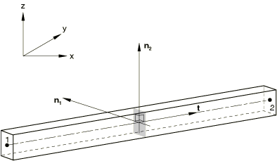
The orientation of a beam cross-section is defined in Abaqus in terms of a local, right-handed (, , ) axis system, where is the tangent to the axis of the element, positive in the direction from
the first to the second node of the element, and and are basis vectors that define the local 1- and 2-directions of the
cross-section. is referred to as the first beam section axis, and is referred to as the normal to the beam. This beam cross-sectional axis
system is illustrated in Figure 1.
Figure 1. Local axis definition for beam-type elements.
Defining the N1-Direction
For beams in a plane the -direction is always (0.0, 0.0, −1.0); that is, normal to the plane in
which the motion occurs. Therefore, planar beams can bend only about the first beam-section
axis.
For beams in space the approximate direction of must be defined directly as part of the beam section definition or by
specifying an additional node off the beam axis as part of the element definition (see Element Definition). This
additional node is included in the element's connectivity list.
If an additional node is specified, the approximate direction of is defined by the vector extending from the first node of the element
to the additional node.
If is defined directly for the section and an additional node is
specified, the direction calculated by using the additional node will take precedence.
If the approximate direction is not defined by either of the above methods, the default
value is (0.0, 0.0, −1.0).
This approximate -direction can be used to determine the -direction (discussed below). Once the -direction has been defined or calculated, the actual -direction will be calculated as , possibly resulting in a direction that is different from the specified
direction.
Input File Usage
Use the following option to specify the -direction directly for a beam section integrated during the
analysis:
BEAM SECTION-direction (the data line number depends on the value of the SECTION parameter)
Use the following option to specify the -direction directly for a general beam section:
BEAM GENERAL SECTION-direction (the data line number depends on the value of the SECTION parameter)
Use the following option to specify an additional node off the beam axis to define the -direction:
Property module: AssignBeam Section Orientation: select region and enter the -direction
Specifying an additional node off the beam axis is not supported in Abaqus/CAE.
Defining Nodal Normals
For beams in space you can define the nodal normal (-direction) by giving its direction cosines as the fourth, fifth, and sixth
coordinates of each node definition or by giving them in a user-specified normal definition;
see Normal Definitions at Nodes for details.
Otherwise, the nodal normal will be calculated by Abaqus, as described below.
If the nodal normal is defined as part of the node definition, this normal is used for all
of the structural elements attached to the node except those for which a user-specified
normal is defined. If a user-specified normal is defined at a node for a particular element,
this normal definition takes precedence over the normal defined as part of the node
definition. If the specified normal subtends an angle that is greater than 20° with the
plane perpendicular to the element axis, a warning message is issued in the data
(.dat) file. If the angle between the normal defined as part of the
node definition or the user-specified normal and is greater than 90°, the reverse of the specified normal is used. This
behavior corresponds to a "rule-based" reversal of user-specified normals. If the default
rule-based reversal of the nodal normal is unexpected, you can specify that the
user-specified nodal normal remain fixed.
Input File Usage
Use the following option to specify the -direction as part of the node definition:
NODEnode number, nodal coordinates, nodal normal coordinates
Use the following option to define a user-specified normal (can be reversed):
Defining the nodal normal is not supported in Abaqus/CAE; the nodal normal calculated by Abaqus is always used.
Calculation of the Average Nodal Normals by Abaqus
If the nodal normal is not defined as part of the node definition, element normal
directions at the node are calculated for all shell and beam elements for which a
user-specified normal is not defined (the “remaining” elements). For shell elements the
normal direction is orthogonal to the shell midsurface, as described in About Shell Elements. For beam elements the normal direction is the
second cross-section direction, as described in Beam Element Cross-Section Orientation. The following algorithm is then used to obtain
an average normal (or multiple averaged normals) for the remaining elements that need a
normal defined:
If a node is connected to more than 30 remaining elements, no averaging occurs and
each element is assigned its own normal at the node. The first nodal normal is stored
as the normal defined as part of the node definition. Each subsequent normal is stored
as a user-specified normal.
If a node is shared by 30 or fewer remaining elements, the normals for all the
elements connected to the node are computed. Abaqus takes one of these elements and puts it in a set with all the other elements that
have normals within 20° of it. Then:
Each element whose normal is within 20° of the added elements is also added to
this set (if it is not yet included).
This process is repeated until the set contains for each element in the set all
the other elements whose normals are within 20°.
If all the normals in the final set are within 20° of each other, an average
normal is computed for all the elements in the set. If any of the normals in the
set are more than 20° out of line from even a single other normal in the set, no
averaging occurs for elements in the set and a separate normal is stored for each
element.
This process is repeated until all the elements connected to the node have had
normals computed for them.
The first nodal normal is stored as the normal defined as part of the node
definition. Each subsequently generated nodal normal is stored as a user-specified
normal.
This algorithm ensures that the nodal averaging scheme has no element order
dependence. A simple example illustrating this process is included below.
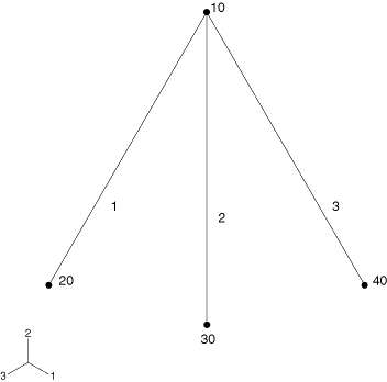
Example: Beam Normal Averaging
Consider the three beam element model in Figure 2. Elements 1, 2, and 3 share a common node 10, with no user-specified normal defined.
Figure 2. Three-element example for nodal averaging algorithm.
In the first scenario, suppose that at node 10 the normal for element 2 is within 20°
of both elements 1 and 3, but the normals for elements 1 and 3 are not within 20° of
each other. In this case, each element is assigned its own normal: one is stored as part
of the node definition and two are stored as user-specified normals.
In the second scenario, suppose that at node 10 the normal for element 2 is within 20°
of both elements 1 and 3 and the normals for elements 1 and 3 are within 20° of each
other. In this case, a single average normal for elements 1, 2, and 3 would be computed
and stored as part of the node definition.
In the last scenario, suppose that at node 10 the normal for element 2 is within 20° of
element 1 but the normal of element 3 is not within 20° of either element 1 or 2. In
this case, an average normal is computed and stored for elements 1, and 2 and the normal
for element 3 is stored by itself: one is stored as part of the node definition and the
other is stored as a user-specified normal.
Appropriate Beam Normals
To ensure proper application of loads that act normal to the beam cross-section, it is
important to have beam normals that correctly define the plane of the cross-section. When
linear beams are used to model a curved geometry, appropriate beam normals are the normals
that are averaged at the nodes. For such cases it is preferable to define the
cross-sectional axis system such that beam normals lie in the plane of curvature and are
properly averaged at the nodes.
Initial Curvature and Initial Twist
In Abaqus/Standard normal direction definitions can result in a beam element having an initial curvature or
an initial twist, which will affect the behavior of some elements.
When the normal to an element is not perpendicular to the beam axis (obtained by
interpolation using the nodes of the element), the beam element is curved. Initial
curvature can result when you define the normal directly (as part of the node definition
or as a user-specified normal) or can result when beams intersect at a node and the
normals to the beams are averaged as described above. The effect of this initial
curvature is considered in cubic beam elements. Initial curvature resulting from normal
definitions is not considered in quadratic beam elements; however, these elements do
properly account for any initial curvature represented by the node positions.
Similarly, nodal-normal directions that are in different orientations about the beam
axis at different nodes imply a twist. The effect of an initial twist, which could
result from normal averaging or user-defined normal definitions, is considered in
quadratic beam elements.
Since the behavior of initially curved or initially twisted beams is quite different from
straight beams, the changes caused by averaging the normals might result in changes in the
deformation of some beam elements. You should always check the model to ensure that the
changes caused by averaging the normals are intended. If the normal directions at successive
nodes subtend an angle that is greater than 20°, a warning message is issued in the data
(.dat) file. In addition, a warning message will be issued during
input file preprocessing if the average curvature computed for a beam differs by more than
0.1 degrees per unit length or if the approximate integrated curvature for the entire beam
differs by more than 5 degrees as compared to the curvature computed without nodal averaging
and without user-defined normals.
In Abaqus/Explicit initial curvature of the beam is not taken into account: all beam elements are assumed to
be initially straight. The element's cross-section orientation is calculated by averaging
the - and -directions associated with its nodes. These two vectors are then projected
onto the plane that is perpendicular to the beam element's axis. These projected directions and are made orthogonal to each other by rotating in this plane by an equal
and opposite angle.