Interaction integral method
In general, the J-integral for a given problem can be written as
where correspond to when indicating the components of B. We define the J-integral for an auxiliary, pure Mode I, crack-tip field with stress intensity factor as
Superimposing the auxiliary field onto the actual field yields
Since the terms not involving or in and J are equal, the interaction integral can be defined as
If the calculations are repeated for Mode and Mode , a linear system of equations results:
If the are assigned unit values, the solution of the above equations leads to
where The calculation of this integral is discussed next.
Based on the definition of the J-integral, the interaction integrals can be expressed as
with given as
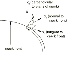
The subscript represents three auxiliary pure Mode I, Mode II, and Mode III crack-tip fields for , respectively. is a contour that lies in the normal plane at position s along the crack front, beginning on the bottom crack surface and ending on the top surface (see Figure 1). The limit indicates that shrinks onto the crack tip.

Following the domain integral procedure used in Abaqus/Standard for calculating the J-integral, we define an interaction integral for a virtual crack advance :
where L denotes the crack front under consideration; is a surface element on a vanishingly small tubular surface enclosing the crack tip (i.e., ); is the outward normal to ; and is the local direction of virtual crack propagation. The integral can be calculated by the same domain integral method as that used for calculating the J-integral.
To obtain at each node set P along the crack front line, is discretized with the same interpolation functions as those used in the finite elements along the crack front:
where at the node set P and all other are zero. The result is substituted into the expression for . Finally, the interaction integral value at each node set P along the crack front can be calculated as