*MATRIX ASSEMBLE | |||||||
|
| ||||||
ProductsAbaqus/Standard
TypeModel data
LevelModel
At least one of the following parameters is required
- MASS
-
Set this parameter equal to the name of the mass matrix.
- STIFFNESS
-
Set this parameter equal to the name of the stiffness matrix.
- STRUCTURAL DAMPING
-
Set this parameter equal to the name of the structural damping matrix.
- VISCOUS DAMPING
-
Set this parameter equal to the name of the viscous damping matrix.
Optional parameters
- NAME
-
This parameter specifies a matrix subassembly name.
If this parameter is omitted, a default name is assigned to each subassembly:
Assemble-1,Assemble-2, etc. - NSET
-
This parameter remaps nodes of the assembled matrices at the usage level. Set this parameter equal to the name of the node set that contains the new node labels corresponding to the matrix nodes. You can map all user-defined nodes of the matrices or the interface nodes only, if defined. The size of the node set and the order of the nodes in the set must fully correspond to the combined set of nodes of all the matrices for all nodes or only interface nodes. If necessary, use an unsorted node set to obtain the correct mapping. The default matrix nodes order is in ascending order of their original labels defined at generation or specified in the matrix data.
If this parameter is omitted, all user-defined nodes retain their original labels.
- POSITION TOL
- Set this parameter equal to the tolerance on the distance between usage level nodes and the corresponding matrix nodes. If this parameter is omitted, the default is a tolerance of 10–4 times the largest estimated characteristic dimension within the matrix subassembly. If the parameter is given with a value of 0.0, the position of the matrix nodes is not checked.
Data lines to translate a matrix subassembly
- First line
-
- TRANSLATE (transformation type).
-
Value of the translation to be applied in the global X-direction.
-
Value of the translation to be applied in the global Y-direction.
-
Value of the translation to be applied in the global Z-direction.
Repeat this data line as often as necessary to define matrix subassembly translations.
Data lines to rotate a matrix subassembly
- First line
-
- ROTATE (transformation type).
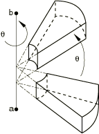
- Global X-coordinate of point a on the axis of rotation (see Figure 1).
- Global Y-coordinate of point a on the axis of rotation.
- Global Z-coordinate of point a on the axis of rotation.
- Global X-coordinate of point b on the axis of rotation.
- Global Y-coordinate of point b on the axis of rotation.
- Global Z-coordinate of point b on the axis of rotation.
- Angle of rotation about the a–b axis (in degrees).
Repeat this data line as often as necessary to define matrix subassembly rotations.
Data lines to reflect a matrix subassembly
- First line
-
- REFLECT (transformation type).
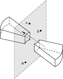
- Global X-coordinate of point a in the plane of reflection (see Figure 2).
- Global Y-coordinate of point a in the plane of reflection.
- Global Z-coordinate of point a in the plane of reflection.
- Global X-coordinate of point b in the plane of reflection.
- Global Y-coordinate of point b in the plane of reflection.
- Global Z-coordinate of point b in the plane of reflection.
- Global X-coordinate of point c in the plane of reflection.
- Global Y-coordinate of point c in the plane of reflection.
- Global Z-coordinate of point c in the plane of reflection.
Repeat this data line as often as necessary to define matrix subassembly reflections.
Data lines to reflect a matrix subassembly using the Euler angles , , and
- First line
-
- EULER (transformation type).
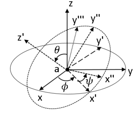
- Precession angle, , of rotation about the -axis (in degrees) (see Figure 3).
- Nutation angle, , of rotation about the -axis (in degrees).
- Intrinsic rotation angle, , of rotation about the -axis (in degrees).
- Global X-coordinate of the reference point, O (optional; default value is zero).
- Global Y-coordinate of the reference point, O (optional; default value is zero).
- Global Z-coordinate of the reference point, O (optional; default value is zero).
Repeat this data line as often as necessary to define matrix subassembly reflections using the Euler angles.


