Creating the cube

To create the cube (the base feature), you create a solid, three-dimensional, extruded part and name it.

Context:

You then sketch its profile (0.04 m × 0.04 m) and extrude the profile over a specified distance (0.04 m) to produce the base feature of the first half of the hinge. The desired cube is shown in Figure 1.
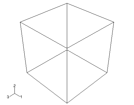
Figure 1. The base feature (a cube) is created first.

Note:

The default render style used throughout Abaqus/CAE is Shaded. For clarity, many of the figures in this tutorial use the wireframe or hidden line render styles. For more information, see Choosing a render style.

  1. Start Abaqus/CAE, and create a new model database. Resize your windows so that you can follow the tutorial and see the Abaqus/CAE main window.

    Abaqus/CAE enters the Part module and displays the Model Tree in the left side of the main window.

  2. In the Model Tree, double-click the Parts container to create a new part.

    The Create Part dialog box appears.

    The text in the prompt area asks you to fill out the Create Part dialog. Abaqus/CAE always displays prompts in the prompt area to guide you through a procedure.

  3. Name the part Hinge-hole. Accept the following default settings:

    • A three-dimensional, deformable body

    • A solid extrusion base feature

  4. In the Approximate size text field, type 0.2. You will be modeling the hinge using meters for the unit of length, and its overall length is 0.14 meters; therefore, 0.2 meters is a sufficiently large approximate size for the part. Click Continue to create the part.

    The Sketcher starts and displays the toolbox between the canvas and the Model Tree. Abaqus/CAE uses the approximate size of the part to compute the default sheet size—0.2 meters in this example. In addition, in this example the Sketcher draws 40 gridlines on the sheet, and the distance between each gridline is 0.005 meters. (You probably see fewer than 40 gridlines because the sheet extends beyond your viewport.)

  5. From the Sketcher toolbox, select the rectangle tool .
  6. Sketch an arbitrary rectangle, and click mouse button 2 in the viewport to exit the rectangle tool.
  7. Dimension the top and left edges so that each is 0.04 m long.

    Important: To complete this tutorial successfully, it is important that you use the dimensions stated and do not deviate from the example; otherwise, you will find it difficult to assemble the model.

  8. Click mouse button 2 to exit the Sketcher.

    Tip: Clicking mouse button 2 in the viewport has the same effect as clicking the default button in the prompt area—Done in this instance.

    Abaqus/CAE displays the Edit Base Extrusion dialog box.

  9. In the dialog box, type a Depth of 0.04 and press Enter.

    Abaqus/CAE exits the Sketcher and displays the base feature, a cube, as shown in Figure 1. The triad in the lower-left corner of the viewport indicates the orientation of the X-, Y-, and Z-axes. You can turn off this triad by selecting ViewportViewport Annotation Options from the main menu bar and toggling off the Show triad option. (The triad is sometimes turned off for clarity in the figures in this tutorial.)

    Note:

    By default, Abaqus/CAE uses the alphabetical option, x-y-z, for labeling the view orientation triad. In general, this guide adopts the numerical option, 1-2-3, to permit direct correspondence with degree of freedom and output labeling. For more information on labeling of axes, see Customizing the view triad.