Nodal offsets in beam sections | ||
| ||

With beam section types I, TRAPEZOID, and ARBITRARY it is possible to specify that the section geometry is located at some distance from the origin of the section's local coordinate system, which is located at the element's nodes. Since it is easy to offset beams with such cross-sections from their nodes, they can be used readily as stiffeners as shown in Figure 1(b). (If flange or web buckling of the stiffeners is important, shells should be used to model the stiffeners.)
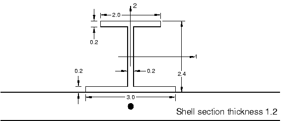
The I-beam shown in Figure 2 is attached to a shell 1.2 units thick. The beam section can be oriented as it is shown in the figure by defining the offset of the beam node from the bottom of the I-section. The offset in this case would be −0.6; i.e., one half of the shell thickness.
You can also specify the location of the centroid and shear center; these locations can be offset from the beam node, thus enabling you to model stiffeners readily.

It is also possible to define the beam nodes and shell nodes separately and connect the beam and shell using a rigid beam constraint between the two nodes. See Linear Constraint Equations for further details.