As discussed in
Symmetric results transfer for a static tire analysis,
it is recommended that the footprint analyses be obtained with a friction
coefficient of zero (so that no frictional forces are transmitted across the
contact surface). The frictional stresses for a rolling tire are very different
from the frictional stresses in a stationary tire, even if the tire is rolling
at very low speed; therefore, discontinuities may arise in the solution between
the last static analysis and the first steady-state transport analysis.
Furthermore, varying the friction coefficient from zero at the beginning of the
steady-state transport step to its final value at the end of the steady-state
transport step ensures that the changes in frictional forces reduce with
smaller load increments. This is important if
Abaqus
must take a smaller load increment to overcome convergence difficulties while
trying to obtain the steady-state rolling solution.
Once the static footprint solution for the tire has been computed, the
steady-state rolling contact problem can be solved using steady-state
transport. The objective of the first simulation in this example is to obtain
the straight line, steady-state rolling solutions, including full braking and
full traction, at different spinning velocities. We also compute the straight
line, free rolling solution. In the second simulation free rolling solutions at
different slip angles are computed. In the first and second simulations
material history effects are ignored by specifying that the long-term behavior
of the material is to be used. The third simulation repeats a portion of the
straight line, steady-state rolling analysis from the first simulation;
however, material history effects are included if you do not specify a
long-term material response. A steady ground velocity of 10.0 km/h is
maintained for all the simulations. The objective of the fourth simulation is
to obtain the free rolling solution of the tire in contact with a 1.5 m rigid
drum rotating at 3.7 rad/s.
In the first simulation (rollingtire_brake_trac.inp)
the full braking solution is obtained in the first steady-state transport step
by setting the friction coefficient, ,
to its final value of 1.0 by changing friction properties and applying the
translational ground velocity together with a spinning angular velocity that
will result in full braking. An estimate of the angular velocity corresponding
to full braking is obtained as follows. A free rolling tire generally travels
farther in one revolution than determined by its center height,
H, but less than determined by the free tire radius. In
this example the free radius is 316.2 mm and the vertical deflection is
approximately 20.0 mm, so
296.2 mm. Using the free radius and the effective height, it is estimated that
free rolling occurs at an angular velocity between
8.78 rad/s and
9.38 rad/s. Smaller angular velocities would result in braking, and larger
angular velocities would result in traction. We use an angular velocity
8.0 rad/s to ensure that the solution in the first steady-state transport step
is a full braking solution (all contact points are slipping, so the magnitude
of the total frictional force across the contact surface is
).
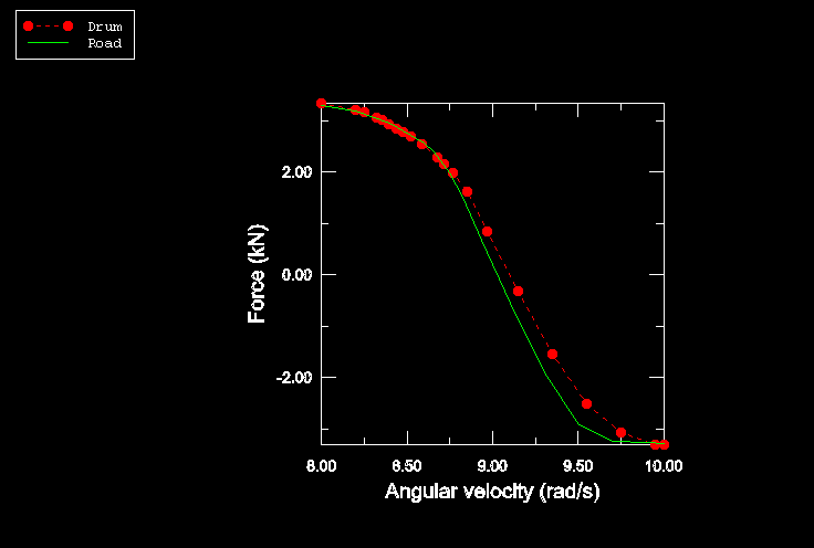
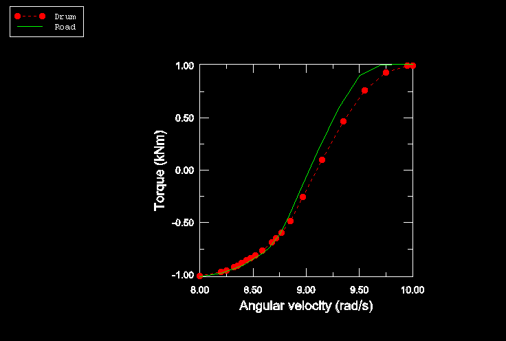
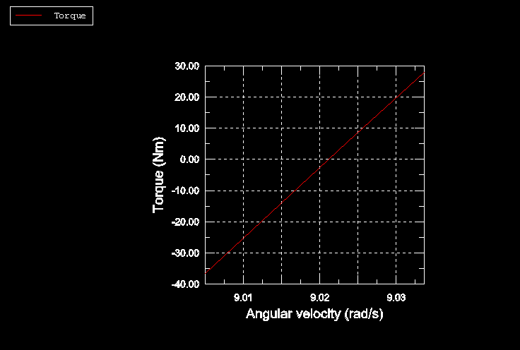
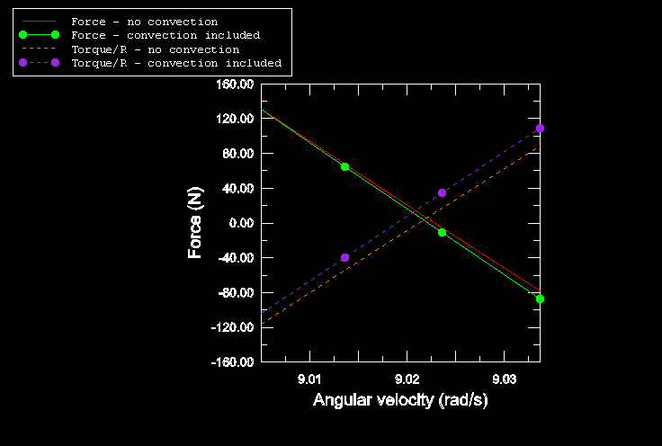
In the second steady-state transport analysis step of the full model, the
angular velocity is increased gradually to
10.0 rad/s while the ground velocity is held constant. The solution at each
load increment is a steady-state solution to the loads acting on the structure
at that instant so that a series of steady-state solutions between full braking
and full traction is obtained. This analysis provides us with a preliminary
estimate of the free rolling velocity. The second simulation
(rollingtire_trac_res.inp) performs a refined search around the first estimate
of free rolling conditions.
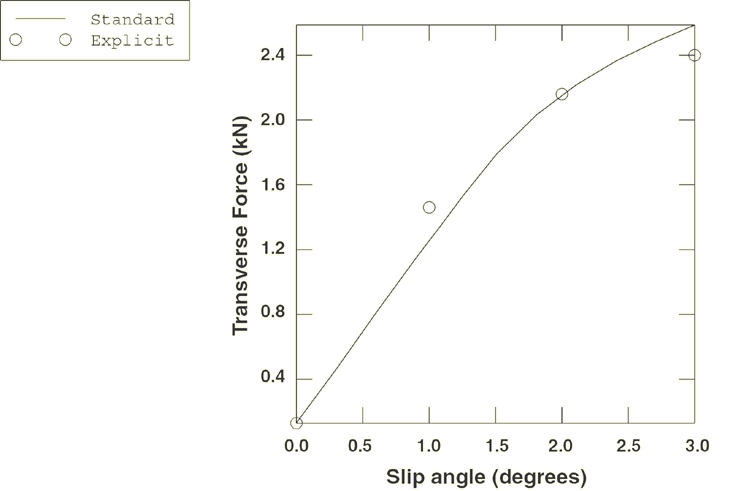
In the third simulation (rollingtire_slipangles.inp)
the free rolling solutions at different slip angles are computed. The slip
angle, ,
is the angle between the direction of travel and the plane normal to the axle
of the tire. In the first step the straight line, free rolling solution from
the first simulation is brought into equilibrium. This step is followed by a
steady-state transport step where the slip angle is gradually increased from
0.0° at the beginning of the step to
3.0° at the end of the step, so a series of steady-state solutions at different
slip angles is obtained. This is accomplished by prescribing a traveling
velocity vector with components
and
in the prescribed translational motion, where
0.0° in the first steady-state transport step and
3.0° at the end of the second steady-state transport step.
The fourth simulation (rollingtire_materialhistory.inp)
includes a series of steady-state solutions between full braking and full
traction in which the material history effects are included.
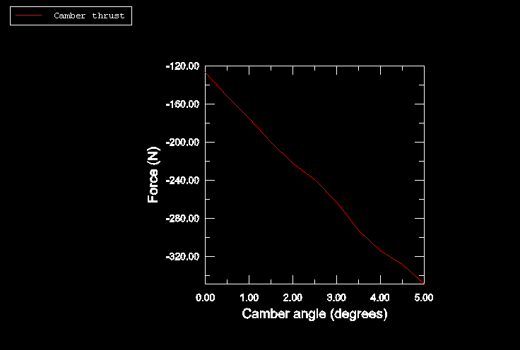
The fifth simulation (rollingtire_camber.inp) analyzes the effect of camber
angle on the lateral thrust at the contact patch under free rolling conditions.
The final simulation in this example (rollingtire_drum.inp)
considers a tire in contact with a rigid rotating drum. The loading sequence is
similar to the loading sequence used in the first simulation. However, in this
simulation the translational velocity of the tire is zero, and a rotational
angular velocity is applied to the reference node of the rigid drum. Since a
prescribed load is applied to the rigid drum reference node to establish
contact between the tire and drum, the rotation axis of the drum is unknown
prior to the analysis.
Abaqus
automatically updates the rotation axis to its current position if the angular
velocity is defined. The rotational velocity of the rigid surface can also be
defined. In that case the position and orientation of the axis of revolution
must be defined in the steady-state configuration and, therefore, must be known
prior to the analysis. The position and orientation of the axis are applied at
the beginning of the step and remain fixed during the step. When the drum
radius is large compared to the axle displacement, as in this example, it is a
reasonable approximation to define the axle in the original configuration
without significantly affecting the accuracy of the results.
