Problem description
The example considers the installation of a concrete liner to support a circular tunnel. Practical geotechnical problems usually involve a complex sequence of construction steps. The construction details determine the appropriate analysis method to represent these steps accurately. Such details have been avoided here for the sake of simplifying the illustration.
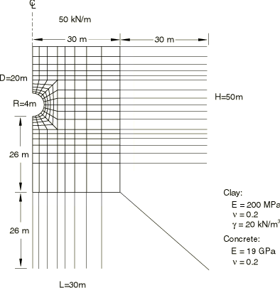
The tunnel is assumed to be excavated in clay, with a Young's modulus of 200 MPa and a Poisson's ratio of 0.2 (see Figure 1). The diameter of the tunnel is 8 m, and the tunnel is excavated 20 m below ground surface. The material surrounding the excavation is discretized with first-order 4-node plane strain elements (element type CPE4). The infinite extent of the soil is represented by a 30-m-wide mesh that extends from the surface to a depth of 50 m below the surface. The left-hand boundary represents a vertical symmetry axis. Far-field conditions on the bottom and right-hand-side boundaries are modeled by infinite elements (element type CINPE4). No mesh convergence studies have been performed to establish if these boundary conditions are placed far enough away from the excavation.
An initial stress field due to gravitational and tectonic forces exists through the depth of the soil. It is assumed that this stress varies linearly with depth and that the ratio between the horizontal and vertical stress components is 0.5. The self weight of the clay is 20.0 kN/m3.
The excavation of the tunnel material is accomplished by applying the forces that are required to maintain equilibrium with the initial stress state in the surrounding material as loads on the perimeter of the tunnel. These loads are then reduced to zero to simulate the excavation. The three-dimensional effect of face advancement during excavation is taken into account by relaxing the forces gradually over several steps. The liner is installed after 40% relaxation of the loads. Further deformation continues to occur as the face of the excavation advances. This ongoing deformation loads the liner.
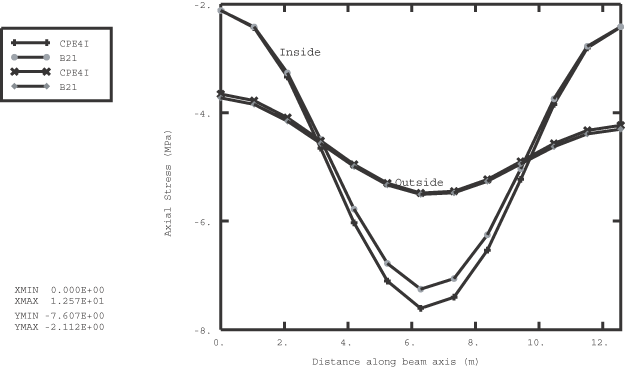
In the first input file the 150-mm-thick liner is discretized with one layer of incompatible mode elements (element type CPE4I). These elements are recommended in regions where bending response must be modeled accurately. In the second input file beam elements are used to discretize the liner. The liner is attached rigidly to the tunnel. The concrete is assumed to have cured to a strength represented by the elastic properties shown in Figure 1 by the time the liner is loaded. The liner is not shown in this diagram.
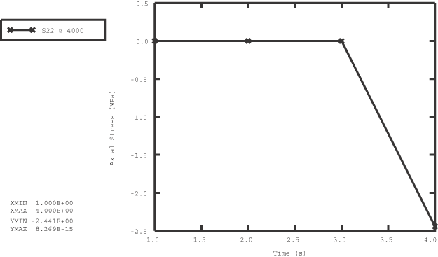
It is expected that an overburden load representing the weight of traffic and buildings exists after the liner is installed.


