Geometry and model
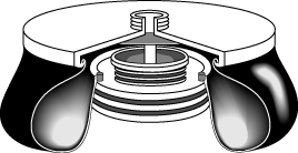
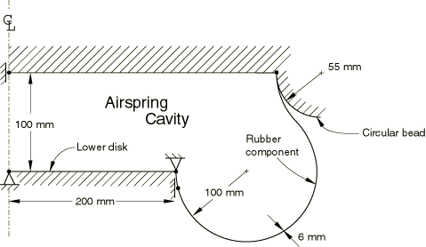
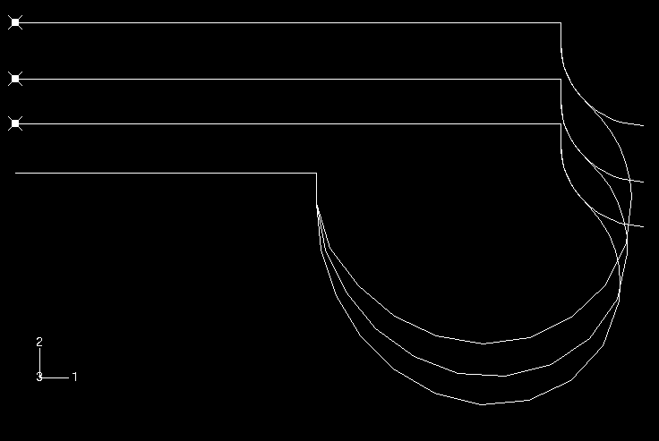
The dimensions of the airspring have been inferred from the paper by Fursdon (1990). This airspring, shown in Figure 1, is fairly large and is used in secondary suspension systems on railway bogies. However, the shape of the airspring is typical of airsprings used in other applications. The airspring's cross-section is shown in Figure 2. The airspring is toroidal in shape, with an inner radius of 200 mm and an outer radius of 400 mm. The airspring has been idealized in the model as consisting of two circular, metal disks connected to each other via a rubber component. The lower disk has a radius of 200 mm, and the upper disk has a radius of 362.11 mm. The disks are initially coaxial and are 100 mm apart. The rubber component is doubly curved and toroidal in shape. The rubber is constrained in the radial direction by a circular bead 55 mm in radius that goes around the circumference of the upper disk.
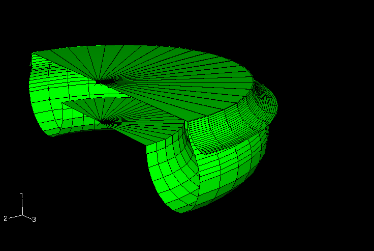
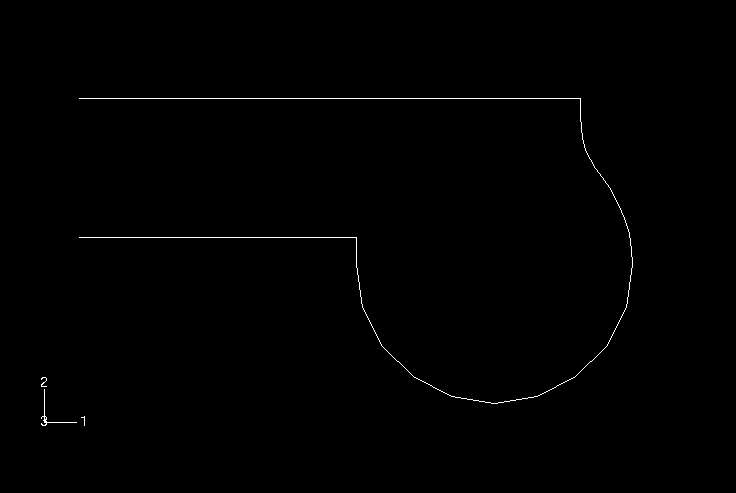
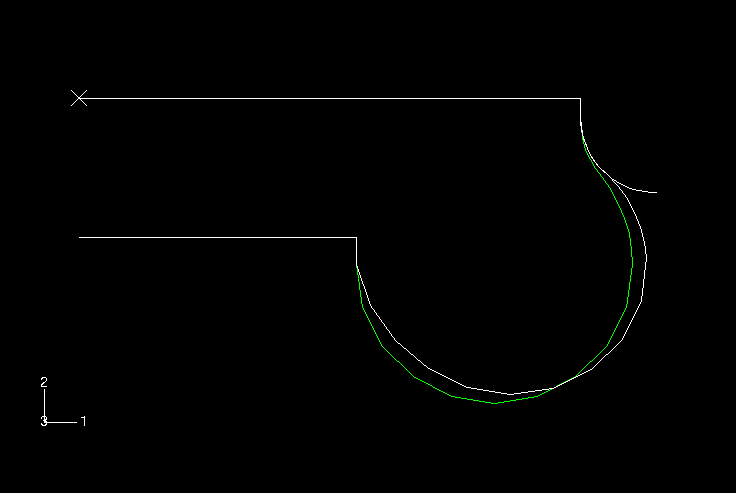
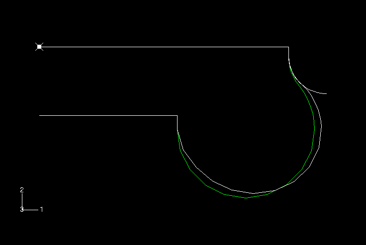
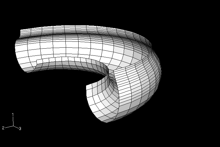
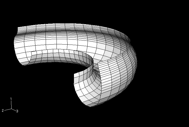
The rubber “hose” in the half-symmetry, three-dimensional model is modeled with 550 S4R finite-strain shell elements. The mesh in the upper hemisphere of the hose is more refined than that in the lower hemisphere, because the rubber membrane undergoes a reversal in curvature in the upper region as it contours the circular bead attached to the upper disk. The circular bead is modeled using an axisymmetric, discrete rigid surface. Contact with the rubber is enforced by defining a contact pair between this rigid surface and a surface defined on the (deformable) shell mesh in the contacting region. The metal disks are assumed to be rigid relative to the rubber component of the airspring. The lower metal disk is modeled using boundary conditions, while the upper disk is modeled as part of the rigid surface. The meshes of the rubber membrane and the rigid surface are shown in Figure 3.
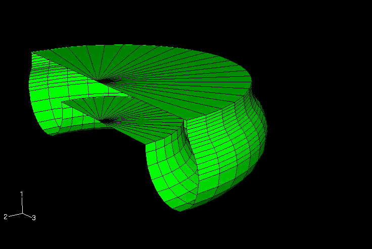
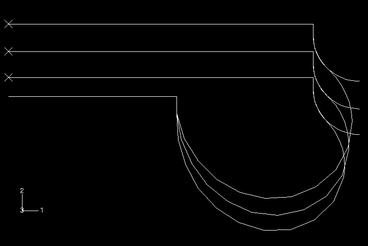
The fluid cavity is modeled using the surface-based fluid cavity capability (see About Surface-Based Fluid Cavities). To define the cavity completely and to ensure proper calculation of its volume, surface elements are defined in the three-dimensional models along the bottom and top rigid disk boundaries of the cavity, even though no displacement elements exist along those surfaces. Since Abaqus does not provide two-dimensional surface elements, the rigid disk boundaries are modeled with structural elements instead of surface elements in the axisymmetric models. The cavity reference node 50000 has a single degree of freedom representing the pressure inside the cavity. Because of symmetry only half of the cavity boundary has been modeled. The cavity reference node has been placed on the model's symmetry plane, y = 0, to assure proper calculation of the cavity volume. Figure 4 shows the mesh of the airspring's cavity.
To facilitate comparisons, the two-dimensional axisymmetric model uses the same cross-sectional mesh refinement as the 180° model. The rubber component is modeled with 25 SAX1 shell elements. The circular bead is modeled with an element-based rigid surface constructed of RAX2 rigid elements. Contact with the hose is enforced by defining a contact pair between this rigid surface and a surface defined on the (deformable) shell mesh in the contacting region. Once again, the lower rigid metal disk is modeled by boundary conditions, and the upper rigid metal disk is modeled as part of the rigid body. The mesh of the rubber membrane and the contact main surface is shown in Figure 5, and the mesh of the cavity is shown in Figure 6. For the membrane model the SAX1 elements are replaced with either MAX1 elements or MGAX1 elements.
