Problem description
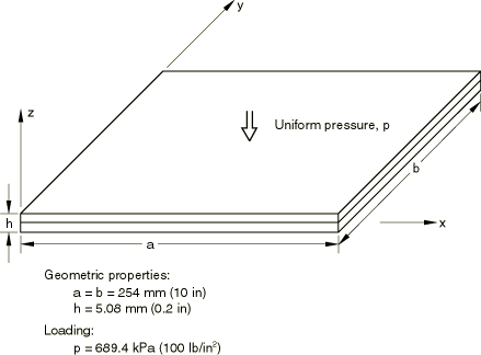
The structure is a two-layer, composite, orthotropic, square plate that is simply supported on its edges. The layers are oriented at 45° with respect to the plate edges. Figure 1 shows the loading and the plate dimensions. Each layer has the following material properties:
| 276 GPa (40 × 106 lb/in2) | |
| 6.9 GPa (106 lb/in2) | |
| 3.4 GPa (0.5 × 10⁶ lb/in2) | |
| 0.25 |
These properties define linear elastic behavior for a lamina under plane stress conditions (Linear Elastic Behavior). More general orthotropic properties (for solid continuum elements) can be specified using the elastic stiffness matrix.
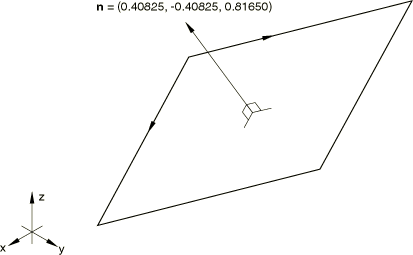
In this example the plate is considered to be at an arbitrary angle to the global axis system to illustrate the use of a local coordinate system. The plate is shown in Figure 2.
The boundary conditions require that displacements that are transverse and normal to the shell edges are fixed, but motions that are parallel to the edges are permitted. A convenient set of local displacement degrees of freedom is defined so that the boundary conditions and the output of nodal variables can be interpreted more easily (Transformed Coordinate Systems).
A local coordinate system is used to define the direction of the layers. The rotation of the material axes of the layers with respect to the standard directions used by Abaqus for stress and strain components in shells is defined in four of the models used and, again for illustration purposes, by means of user subroutine ORIENT in four other models. The section is not balanced since it has only two layers in different orientations, which results in membrane-bending coupling. The motion does not exhibit symmetry for the same reason, and the entire shell must be modeled.
An alternative means of defining the layer orientation is to use a local coordinate to define the orientation of the section and then to define the in-plane angle of rotation relative to the section orientation directly with the layer data in the shell section or general shell section definition. In this case the section force and section strain are calculated in the section orientation directions (rather than the default shell directions).
Three types of models are used. One is an 8 × 8 mesh of S9R5 elements, which are shell elements that allow transverse shear along lines in the element. However, the analytical solution of Spilker et al. uses thin shell theory, which neglects transverse shear effects. We have, therefore, introduced an artificially high transverse shear stiffness in this model.
The second type of model is a 16 × 16 mesh of triangular shells; models for both S3R and SC6R elements are provided. These elements are general-purpose shell elements that allow transverse shear deformation. An artificially high transverse shear stiffness is introduced. No mesh convergence studies have been performed, but finer meshes should improve accuracy since these elements use a constant bending strain approximation.
The third type of model is made up of STRI65 shell elements, which are also based on the discrete Kirchhoff theory. An 8 × 8 mesh is used.


