*THREADED INTERFACE | |||||||
|
| ||||||
Products Abaqus/Standard
Type Model data
LevelModel
Required parameters
- NAME
-
Set this parameter equal to a label that is used to refer to this threaded interface definition.
Optional parameters
- AXIS
-
Set AXIS=AUTOMATIC (default) to use the axis calculated internally from the nominal surface of the externally threaded (bolt or bolt-like) part and the nominal surface of the internally threaded (nut or nut-like) part.
Set AXIS=EXTERNAL THREAD POINTS to use the axis specified by the user-specified points for the external threads.
Set AXIS=INTERNAL THREAD POINTS to use the axis specified by the user-specified points for the internal threads.
- EXTERNAL THREAD EXTENT
-
Set EXTERNAL THREAD EXTENT=AUTOMATIC (default) to use the external thread extent calculated internally from the nominal surface of the externally threaded part.
Set EXTERNAL THREAD EXTENT=SPECIFY POINTS to use the external thread extent specified by the user-specified points for the external threads.
- FACETS
-
Set FACETS=QUADRATIC (default) to use second-order surface elements for the automatically generated thread meshes.
Set FACETS=LINEAR to use first-order surface elements for the automatically generated thread meshes.
- HANDEDNESS
-
Set HANDEDNESS=RIGHT (default) to select the right-handed thread geometry.
Set HANDEDNESS=LEFT to select the left-handed thread geometry.
- INTERNAL THREAD EXTENT
-
Set INTERNAL THREAD EXTENT=AUTOMATIC (default) to use the internal thread extent internally calculated from the nominal surface of the internally threaded part.
Set INTERNAL THREAD EXTENT=SPECIFY POINTS to use the internal thread extent specified by the user-specified points for the internal threads.
- POINTS
-
Set POINTS=COORDINATES (default) to provide coordinates to control the axial range over which threads are generated and/or to specify the threads axis.
Set POINTS=NODES to provide nodes to control the axial range over which threads are generated and/or to specify the threads axis.
Data lines to specify the threaded interface parameters with POINTS=COORDINATES
- First line (see Figure 1 below)
-
Half thread angle, (in degrees). The default is 30°
Pitch (thread-to-thread distance), .
- Second line (optional, see Figure 1 below)
-
Initial radial clearance distance: A positive value indicates an opening between the external and the internal threads. If this field is left blank, a default clearance is calculated (see Automatically Generated Surface Element Representations of Threads).
External thread diameter, . The default value is the diameter of the nominal surface of the externally threaded part.
Specify MEAN (default), MINOR, or MAJOR to interpret the second entry as the mean diameter, ; minimum (minor) diameter, ; or maximum (major) diameter, of the automatically generated external threads, respectively.
Omit this entry if a clearance value is specified. Specify MEAN (default), MINOR, or MAJOR to interpret the diameter of the nominal surface of the internally threaded part to correspond to the mean diameter, minor diameter, or the major diameter of the automatically generated internal threads, respectively.
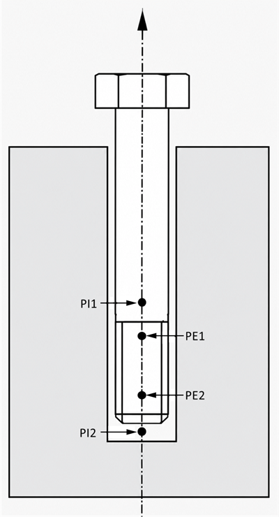
- Third line to control the axial range over which external threads are generated if EXTERNAL THREAD EXTENT=SPECIFY POINTS and/or to specify the threads axis if AXIS= EXTERNAL THREAD POINTS (optional, see Figure 2 below)
-
Global X-coordinate of point PE1.
Global Y-coordinate of point PE1.
Global Z-coordinate of point PE1.
Global X-coordinate of point PE2.
Global Y-coordinate of point PE2.
Global Z-coordinate of point PE2.
- Fourth line to control the axial range over which internal threads are generated if INTERNAL THREAD EXTENT=SPECIFY POINTS and/or to specify the threads axis if AXIS= INTERNAL THREAD POINTS (optional, see Figure 2 below)
-
Global X-coordinate of point PI1.
Global Y-coordinate of point PI1.
Global Z-coordinate of point PI1.
Global X-coordinate of point PI2.
Global Y-coordinate of point PI2.
Global Z-coordinate of point PI2.
Data lines to specify the threaded interface parameters if POINTS=NODES
- First line (see Figure 1 below)
-
Half thread angle, (in degrees). The default is 30°
Pitch (thread-to-thread distance), .
- Second line (optional, see Figure 1 below)
-
Clearance value: A positive value indicates an opening between the external and the internal threads. If this field is left blank, a default clearance is calculated (see Automatically Generated Surface Element Representations of Threads).
External thread diameter, . The default value is the diameter of the nominal surface of the externally threaded part.
Specify MEAN (default), MINOR, or MAJOR to interpret the second entry as the mean diameter, ; minimum (minor) diameter, ; or maximum (major) diameter, of the automatically generated external threads, respectively.
Omit this entry if a clearance value is specified. Specify MEAN (default), MINOR, or MAJOR to interpret the diameter of the nominal surface of the internally threaded part to correspond to the mean diameter, minor diameter, or the major diameter of the automatically generated internal threads, respectively.
- Third line to control the axial range over which external threads are generated if EXTERNAL THREAD EXTENT=SPECIFY POINTS and/or to specify the threads axis if AXIS= EXTERNAL THREAD POINTS (optional, see Figure 2 below)
-
Node number of the node at point PE1.
Node number of the node at point PE2.
- Fourth line to control the axial range over which internal threads are generated if INTERNAL THREAD EXTENT=SPECIFY POINTS and/or to specify the threads axis if AXIS= INTERNAL THREAD POINTS (optional, see Figure 2 below)
-
Node number of the node at point PI1.
Node number of the node at point PI2.