describes the inelastic behavior of the material by a yield function that depends on the
three stress invariants, an associated flow assumption to define the plastic strain rate,
and a strain hardening theory that changes the size of the yield surface according to the
inelastic volumetric strain;
can have an isotropic or an anisotropic yield function;
requires that the elastic part of the deformation be defined by using the isotropic or
orthotropic linear elastic material model (Linear Elastic Behavior) or,
in Abaqus/Standard, the porous elastic material model (Elastic Behavior of Porous Materials) within
the same material definition (porous elasticity is supported only for isotropic yield
functions);
allows for the hardening law to be defined by a piecewise linear form or, in Abaqus/Standard, by an exponential form;
Might optionally include hardening in hydrostatic tension; and
can be used in conjunction with a regularization scheme for mitigating mesh dependence in
situations where the material exhibits strain localization with increasing plastic
deformation.
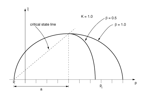
is a constant that defines the slope of the critical state line;
is a constant that is equal to 1.0 on the “dry” side of the critical state line () but might be different from 1.0 on the “wet” side of the critical
state line ( introduces a different ellipse on the wet side of the critical state
line; that is, a tighter “cap” is obtained if as shown in Figure 1);
is a measure of the size of the yield surface (Figure 1);
is the yield stress in hydrostatic compression;
is the yield stress in hydrostatic tension; and
K
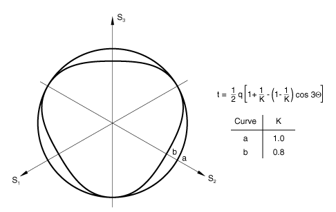
is the ratio of the flow stress in triaxial tension to the flow stress in triaxial
compression and determines the shape of the yield surface in the plane of principal
deviatoric stresses (the “-plane”: see Figure 2); Abaqus requires that to ensure that the yield surface remains convex.
The user-defined parameters M, , and K can depend on temperature as well as other predefined field variables, . For the isotropic model, the expression for reduces to the Mises equivalent stress, . The model is described in detail in Critical state models.
Figure 1. Clay yield surfaces in the – plane. Figure 2. Isotropic clay yield surface sections in the -plane ( and for the isotropic yield function).
Input File Usage
Use the following option to define the isotropic model:
The hardening law can have an exponential form (Abaqus/Standard only) or a piecewise linear form.
Exponential Form in Abaqus/Standard
The exponential form of the hardening law can be used only in conjunction with the Abaqus/Standard porous elastic material model and the isotropic form of the yield surface with . The size of the yield surface at any time is determined by the initial
value of the hardening parameter, , and the amount of inelastic volume change that occurs according to the
equation
where
is the inelastic volume change (that part of J, the ratio of
current volume to initial volume, attributable to inelastic deformation);
is the logarithmic bulk modulus of the material defined for the porous elastic
material behavior;
is the logarithmic hardening constant defined for the clay plasticity material
behavior; and
Specifying the Initial Size of the Yield Surface Directly
The initial size of the yield surface is defined for clay plasticity by specifying the
hardening parameter, , as a tabular function or by defining it analytically.
can be defined along with , M, , and K, as a tabular function of temperature and
other predefined field variables. However, is a function only of the initial conditions; it will not change if
temperatures and field variables change during the analysis.
Property module: material editor:
MechanicalElasticityPorous ElasticMechanicalPlasticityClay Plasticity: Hardening: Exponential
Load module: Create Predefined Field: Step: Initial: choose Other for the Category and Void ratio for the Types for Selected Step
Specifying the Initial Size of the Yield Surface Indirectly
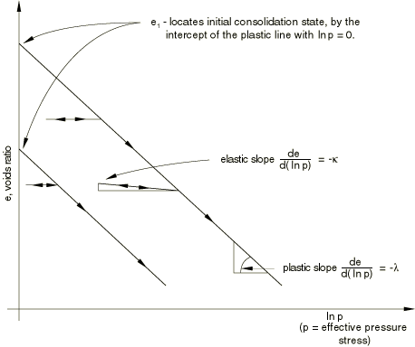
The hardening parameter can be defined indirectly by specifying , which is the intercept of the virgin consolidation line with the void
ratio axis in the plot of void ratio, e, versus the logarithm of
the effective pressure stress, (Figure 3).
Figure 3. Pure compression behavior for clay model.
If this method is used, is defined by
where is the user-defined initial value of the equivalent hydrostatic
pressure stress (see Defining Initial Stresses). You define , , M, , and K; all the parameters except can be dependent on temperature and other predefined field variables.
However, is a function only of the initial conditions; it will not change if
temperatures and field variables change during the analysis.
Property module: material editor:
MechanicalElasticityPorous ElasticMechanicalPlasticityClay Plasticity: Hardening: Exponential, Intercept:
Load module: Create Predefined Field: Step: Initial: choose Other for the Category and Void ratio for the Types for Selected Step
Load module: Create Predefined Field: Step: Initial: choose Other for the Category and Stress for the Types for Selected Step
Piecewise Linear Form
If the piecewise linear form of the hardening rule is used, the user-defined relationship
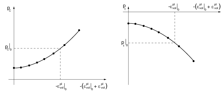
relates the yield stress in hydrostatic compression, , and, optionally, the yield stress in hydrostatic tension, , to the corresponding volumetric plastic strain, (Figure 4):
Figure 4. Typical piecewise linear clay hardening/softening curve.
The evolution parameter, a, is then given by
The volumetric plastic strain axis has an arbitrary origin: is the position on this axis corresponding to the initial state of the
material, thus defining the initial hydrostatic pressure in compression, , and, optionally, in tension, and, hence, the initial yield surface size, . This relationship is defined in tabular form as clay hardening data.
The range of values for which and is defined should be sufficient to include all values of equivalent
pressure stress to which the material will be subjected during the analysis. Data for must be specified; data for is optional.
This form of the hardening law can be used in conjunction with either the linear elastic
or, in Abaqus/Standard, the porous elastic material models. This is the only form of the hardening law
supported in Abaqus/Explicit.
Input File Usage
Use both of the following options to define the hardening behavior by providing the
hydrostatic compression yield stress as a function of volumetric plastic strain:
Optionally, add the following option to define the tensile hardening behavior by
providing the hydrostatic tension yield stress as a function of volumetric plastic
strain:
Granular materials often exhibit strain localization with increasing plastic deformation.
Post-failure solutions from conventional finite element methods can be strongly mesh
dependent. To mitigate the mesh dependency of the solutions, a regularization method is
often used to introduce a micro-structural length scale into the constitutive formulation.
Let denote the characteristic width of a shear band or a crack band, the characteristic length of the element, and the inelastic strain for the element. Then the inelastic strain in the
localization band, , is defined to be
where is a material parameter and is a positive number used for bounding the magnitude of regularization.
This strain regularization method is valid only when the characteristic length of the
element is greater than the width of the localization band; that is, .
If softening regularization is included, it is applied to all hardening data (tension and
compression) by default. You can optionally turn off softening regularization for a specific
type of hardening.
Input File Usage
Use the following options to include softening regularization:
Use the following options to include softening regularization:
Property module: material editor: MechanicalPlasticityClay Plasticity: SuboptionsSoftening Regularization
Calibration
At least two experiments are required to calibrate the simplest version of the Cam-clay
model: a hydrostatic compression test (an oedometer test is also acceptable) and a triaxial
compression test (more than one triaxial test is useful for a more accurate calibration).
Hydrostatic Compression Tests
The hydrostatic compression test is performed by pressurizing the sample equally in all
directions. The applied pressure and the volume change are recorded.
The onset of yielding in the hydrostatic compression test immediately provides the
initial position of the yield surface, . The logarithmic bulk moduli, and , are determined from the hydrostatic compression experimental data by
plotting the logarithm of pressure versus void ratio. The void ratio,
e, is related to the measured volume change as
The slope of the line obtained for the elastic regime is , and the slope in the inelastic range is . For a valid model .
Triaxial Tests
Triaxial compression experiments are performed using a standard triaxial machine where a
fixed confining pressure is maintained while the differential stress is applied. Several
tests covering the range of confining pressures of interest are usually performed. Again,
the stress and strain in the direction of loading are recorded, together with the lateral
strain so that the correct volume changes can be calibrated.
The triaxial compression tests allow the calibration of the yield parameters
M and . M is the ratio of the shear stress,
q, to the pressure stress, p, at critical
state and can be obtained from the stress values when the material has become perfectly
plastic (critical state). represents the curvature of the cap part of the yield surface and can be
calibrated from a number of triaxial tests at high confining pressures (on the “wet” side
of critical state). must be between 0.0 and 1.0.
To calibrate the parameter K, which controls the yield dependence on
the third stress invariant, experimental results obtained from a true triaxial (cubical)
test are necessary. These results are generally not available, and you might have to guess
(the value of K is generally between 0.8 and 1.0) or ignore this
effect.
To calculate the yield stress in hydrostatic tension, you can plot the data obtained from
the triaxial compression tests on the – plane and extend the curve obtained from fitting these experimental data
to the pressure axis in the tensile region.
Unloading Measurements
Unloading measurements in hydrostatic and triaxial compression tests are useful to
calibrate the elasticity, particularly in cases where the initial elastic region is not
well defined. From these we can identify whether a constant shear modulus or a constant
Poisson's ratio should be used and what their values are.
Initial Conditions
If an initial stress at a point is given (see Defining Initial Stresses) such that the stress point lies outside the initially defined yield surface, Abaqus will try to adjust the initial position of the surface to make the stress point lie on it
and issue a warning. However, if the yield stress in hydrostatic tension, , is zero and does not evolve with volumetric plastic strain and the stress
point is such that the equivalent pressure stress, p, is negative, an
error message will be issued and execution will be terminated.
The initial condition on volumetric plastic strain, , can be defined in the definition of the clay plasticity model. Abaqus also allows a general method of specifying the initial plastic strain field on elements
(see Defining Initial Values of Plastic Strain). The volumetric plastic strain is then calculated as
Elements
The clay plasticity model can be used with plane strain, generalized plane strain,
axisymmetric, and three-dimensional solid (continuum) elements in Abaqus. This model cannot be used with elements for which the assumed stress state is plane
stress (plane stress, shell, and membrane elements).