Defining the Constitutive Response of Cohesive Elements Using a Traction-Separation
Description
The features described in this section are primarily intended for bonded interfaces
where the interface thickness is negligibly small. In such cases it might be straightforward
to define the constitutive response of the cohesive layer directly in terms of traction versus
separation.
If the interface adhesive layer has a finite thickness and macroscopic properties (such as
stiffness and strength) of the adhesive material are available, it might be more appropriate
to model the response using conventional material models. The former approach is discussed in
this section, while the latter approach is discussed in Defining the Constitutive Response of Cohesive Elements Using a Continuum Approach.
Cohesive behavior defined directly in terms of a traction-separation law:
can be used to model the delamination at interfaces in composites directly in terms of
traction versus separation;
allows specification of material data such as the fracture energy as a function of the
ratio of normal to shear deformation (mode mix) at the interface;
assumes a linear elastic traction-separation law prior to damage;
Defining Constitutive Response in Terms of Traction-Separation Laws
To define the constitutive response of the cohesive element directly in terms of traction
versus separation, you choose a traction-separation response when defining the section
behavior of the cohesive elements.
Property module: Create Section: select Other as the section Category and Cohesive as the section Type: Response: Traction Separation
Linear Elastic Traction-Separation Behavior
The available traction-separation model in Abaqus assumes initially linear elastic behavior (see Defining Elasticity in Terms of Tractions and Separations for Cohesive Elements) followed by the
initiation and evolution of damage. The elastic behavior is written in terms of an elastic
constitutive matrix that relates the nominal stresses to the nominal strains across the
interface. The nominal stresses are the force components divided by the original area at
each integration point. The nominal strains are the separations divided by the original
thickness at each integration point with some averaging applied to the transverse shear
components. The default value of the original constitutive thickness is 1.0 if
traction-separation response is specified, which ensures that the nominal strain is equal to
the separation (that is, relative displacements of the top and bottom faces). The
constitutive thickness used for traction-separation response is typically different from the
geometric thickness (which is typically close or equal to zero). See Specifying the Constitutive Thickness for a discussion on
how to modify the constitutive thickness.
The nominal traction stress vector, , consists of three components (two components in two-dimensional
problems): , , and (in three-dimensional problems) , which represent the normal (along the local 3-direction in three
dimensions and along the local 2-direction in two dimensions) and the two shear tractions
(along the local 1- and 2-directions in three dimensions and along the local 1-direction in
two dimensions), respectively. The corresponding separations are denoted by , , and . Denoting by the original thickness of the cohesive element, the nominal strains can be
defined as
The elastic behavior can then be written as
The elasticity matrix provides fully coupled behavior between all components of the
traction vector and separation vector and can depend on temperature and field variables. Set
the off-diagonal terms in the elasticity matrix to zero if uncoupled behavior between the
normal and shear components is required.
Optionally, for the uncoupled traction behavior a compression factor can be specified; this
ensures that the compressive stiffness is equal to the specified factor times the tensile
stiffness, . This factor affects only the traction response for separation in the
normal direction; the shear behavior is not affected.
Input File Usage
Use the following option to define uncoupled traction-separation behavior:
Use the following option to define uncoupled traction-separation behavior:
Property module: material editor: MechanicalElasticityElastic: Type: Traction
Use the following option to define coupled traction-separation behavior:
Property module: material editor: MechanicalElasticityElastic: Type: Coupled Traction
Specifying a compression factor for uncoupled traction-separation behavior is not
supported in Abaqus/CAE.
Interpretation of Material Properties
The material parameters, such as the interfacial elastic stiffness, for a
traction-separation model can be better understood by studying the equation that represents
the displacement of a truss of length L, elastic stiffness
E, and original area A, due to an axial load
P:
This equation can be rewritten as
where is the nominal stress and is the stiffness that relates the nominal stress to the displacement.
Likewise, the total mass of the truss, assuming a density , is given by
The above equations suggest that the actual length L can be replaced
with 1.0 (to ensure that the strain is the same as the displacement) if the stiffness and
the density are appropriately reinterpreted. In particular, the stiffness is and the density is , where the true length of the truss is used in these equations. The
density represents mass per unit area instead of mass per unit volume.
These ideas can be carried over to a cohesive layer of initial thickness . If the adhesive material has stiffness and density , the stiffness of the interface (relating the nominal traction to the
nominal strain) is given by and the density of the interface is given by . As discussed earlier, the default choice of the constitutive thickness for modeling the response in terms of traction versus separation is 1.0
regardless of the actual thickness of the cohesive layer. With this choice, the nominal
strains are equal to the corresponding separations. When the constitutive thickness of the
cohesive layer is “artificially” set to 1.0, ideally you should specify and (if needed) as the material stiffness and density, respectively, as
calculated with the true thickness of the cohesive layer.
The above formulas provide a recipe for estimating the parameters required for modeling the
traction-separation behavior of an interface in terms of the material properties of the bulk
adhesive material. As the thickness of the interface layer tends to zero, the above
equations imply that the stiffness, , tends to infinity and the density, , tends to zero. This stiffness is often chosen as a penalty parameter. A
very large penalty stiffness is detrimental to the stable time increment in Abaqus/Explicit and might result in ill-conditioning of the element operator in Abaqus/Standard. Recommendations for the choice of the stiffness and density of an interface for an Abaqus/Explicit analysis such that the stable time increment is not adversely affected are provided in
Stable Time Increment in Abaqus/Explicit.
Modeling Viscoelastic Traction-Separation Behavior in Abaqus/Explicit
Time domain viscoelasticity can be used in Abaqus/Explicit to model rate-dependent behavior of cohesive elements with traction-separation
elasticity. The evolution equation for the normal and two shear nominal tractions take the
form:
where , , and are the instantaneous nominal tractions at time t in
the normal and the two local shear directions, respectively. The functions and represent the dimensionless shear and normal relaxation moduli,
respectively. See Defining Viscoelastic Behavior for Traction-Separation Elasticity in Abaqus/Explicit for additional
details and usage information.
You can also combine time domain viscoelasticity with the models for rate-dependent
progressive damage and failure described in the next sections. This combination allows
modeling rate-dependent behavior both during the initial elastic response (prior to damage
initiation), as well as during damage progression.
Damage Modeling
Both Abaqus/Standard and Abaqus/Explicit allow modeling of progressive damage and failure in cohesive layers whose response is
defined in terms of traction-separation. By comparison, only Abaqus/Explicit allows modeling of progressive damage and failure for cohesive elements modeled with
conventional materials (Defining the Constitutive Response of Cohesive Elements Using a Continuum Approach). Damage of the
traction-separation response is defined within the same general framework used for
conventional materials (see About Progressive Damage and Failure). This general
framework allows the combination of several damage mechanisms acting simultaneously on the
same material. Each failure mechanism consists of three ingredients: a damage initiation
criterion, a damage evolution law, and a choice of element removal (or deletion) on reaching
a completely damaged state. While this general framework is the same for traction-separation
response and conventional materials, many details of how the various ingredients are defined
are different. Therefore, the details of damage modeling for traction-separation response
are presented below.
The initial response of the cohesive element is assumed to be linear as discussed above.
However, once a damage initiation criterion is met, material damage can occur according to a
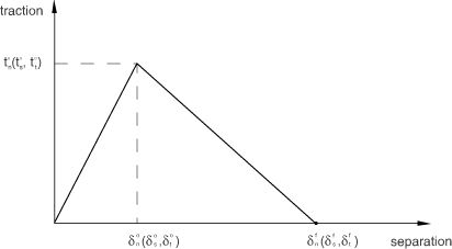
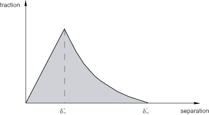
user-defined damage evolution law. Figure 1 shows a typical traction-separation response with a failure mechanism. If the damage
initiation criterion is specified without a corresponding damage evolution model, Abaqus will evaluate the damage initiation criterion for output purposes only; there is no
effect on the response of the cohesive element (that is, no damage will occur). The cohesive
layer does not undergo damage under pure compression.
Figure 1. Typical traction-separation response.
Damage Initiation
As the name implies, damage initiation refers to the beginning of degradation of the
response of a material point. The process of degradation begins when the stresses and
strains satisfy certain damage initiation criteria that you specify. Several damage
initiation criteria are available and are discussed below. Each damage initiation criterion
also has an output variable associated with it to indicate whether the criterion is met. A
value of 1 or higher indicates that the initiation criterion has been met (see Output for further
details). Damage initiation criteria that do not have an associated evolution law affect
only output. Thus, you can use these criteria to evaluate the propensity of the material to
undergo damage without actually modeling the damage process (that is, without actually
specifying damage evolution).
In the discussion below, , , and represent the peak values of the nominal stress when the deformation is
either purely normal to the interface or purely in the first or the second shear direction,
respectively. Likewise, , , and represent the peak values of the nominal strain when the deformation is
either purely normal to the interface or purely in the first or the second shear direction,
respectively. With the initial constitutive thickness , the nominal strain components are equal to the respective components of
the relative displacement—, , and —between the top and bottom of the cohesive layer. The symbol used in the discussion below represents the Macaulay bracket with the
usual interpretation. The Macaulay brackets are used to signify that a pure compressive
deformation or stress state does not initiate damage.
Maximum Nominal Stress Criterion
Damage is assumed to initiate when the maximum nominal stress ratio (as defined in the
expression below) reaches a value of one. This criterion can be represented as
Property module: material editor: MechanicalDamage for Traction-Separation LawsMaxs Damage
Maximum Nominal Strain Criterion
Damage is assumed to initiate when the maximum nominal strain ratio (as defined in the
expression below) reaches a value of one. This criterion can be represented as
Property module: material editor: MechanicalDamage for Traction-Separation LawsMaxe Damage
Quadratic Nominal Stress Criterion
Damage is assumed to initiate when a quadratic interaction function involving the nominal
stress ratios (as defined in the expression below) reaches a value of one. This criterion
can be represented as
Property module: material editor: MechanicalDamage for Traction-Separation LawsQuads Damage
Quadratic Nominal Strain Criterion
Damage is assumed to initiate when a quadratic interaction function involving the nominal
strain ratios (as defined in the expression below) reaches a value of one. This criterion
can be represented as
Property module: material editor: MechanicalDamage for Traction-Separation LawsQuade Damage
Rate-Dependent Damage Initiation in Abaqus/Explicit
In Abaqus/Explicit you can define the damage initiation criteria as a function of the effective rate of
separation. You can combine this definition with rate-dependent damage evolution to
describe the rate-dependent delamination behavior for a cohesive interface.
Input File Usage
Use the following option to specify rate-dependent damage initiation:
Rate-dependent damage initiation is not supported in Abaqus/CAE.
Damage Evolution
The damage evolution law describes the rate at which the material stiffness is degraded
once the corresponding initiation criterion is reached. The general framework for describing
the evolution of damage in bulk materials (as opposed to interfaces modeled using cohesive
elements) is described in Damage Evolution and Element Removal for Ductile Metals. Conceptually,
similar ideas apply for describing damage evolution in cohesive elements with a constitutive
response that is described in terms of traction versus separation; however, many details are
different.
A scalar damage variable, D, represents the overall damage in the
material and captures the combined effects of all the active mechanisms. It initially has a
value of 0. If damage evolution is modeled, D monotonically evolves
from 0 to 1 on further loading after the initiation of damage. The stress components of the
traction-separation model are affected by the damage according to
where , and are the stress components predicted by the elastic traction-separation
behavior for the current strains without damage.
To describe the evolution of damage under a combination of normal and shear deformation
across the interface, it is useful to introduce an effective displacement (Camanho and
Davila, 2002) defined as
The equivalent nominal strain can be defined as
Mixed-Mode Definition
The mode mix of the deformation fields in the cohesive zone quantify the relative
proportions of normal and shear deformation. Abaqus uses three measures of mode mix, two that are based on energies and one that is based
on tractions. You can choose one of these measures when you specify the mode dependence of
the damage evolution process. Denoting by , , and the work done by the tractions and their conjugate relative
displacements in the normal, first, and second shear directions, respectively, and
defining , the mode mix definitions based on energies are as follows:
Clearly, only two of the three quantities defined above are independent. It is also
useful to define the quantity to denote the portion of the total work done by the shear traction and
the corresponding relative displacement components. As discussed later, Abaqus requires that you specify material properties related to damage evolution as functions
of (or, equivalently, ) and .
Abaqus computes the energy quantities described above either based on the current state of
deformation (nonaccumulative measure of energy) or based on the deformation history
(accumulative measure of energy) at an integration point. The former approach is useful in
mixed-mode simulations where the primary energy dissipation mechanism is associated with
the creation of new surfaces due to failure in the cohesive zone. Typically, such problems
are adequately described utilizing the methods of linear elastic fracture mechanics. The
latter approach provides an alternate way of defining the mode mix and might be useful in
situations where other significant dissipation mechanisms also govern the overall
structural response.
The corresponding definitions of the mode mix based on traction components are given by
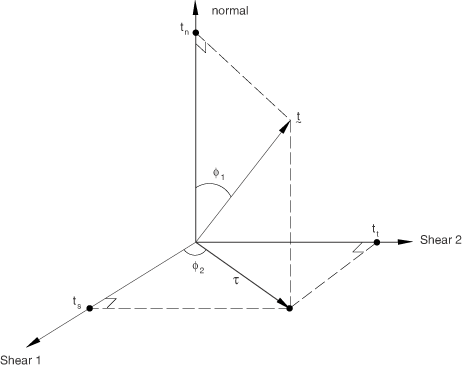
where is a measure of the effective shear traction. The angular measures used
in the above definition (before they are normalized by the factor ) are illustrated in Figure 2.
Figure 2. Mode mix measures based on traction.
Input File Usage
Use the following option to use the mode mix definition based on nonaccumulated
energies:
Property module: material editor: MechanicalDamage for Traction-Separation LawsQuade Damage, Maxe Damage, Quads Damage, or
Maxs Damage: SuboptionsDamage Evolution: Mode mix ratio:Energy or
Traction
Specifying a mode mix definition based on accumulated energies is not supported in
Abaqus/CAE.
Comparison of Mixed-Mode Definitions
The mode mix ratios defined in terms of the different energy quantities and tractions
can be quite different in general. The following examples illustrate this point. In
terms of energies a deformation in the purely normal direction is one for which and , irrespective of the values of the normal and the shear tractions. In
particular, for a material with coupled traction-separation behavior both the normal and
shear tractions might be nonzero for a deformation in the purely normal direction. For
this case the definition of mode mix based on energies would indicate a purely normal
deformation, while the definition based on tractions would suggest a mix of both normal
and shear deformation.
When the mode mix is defined based on accumulated energies, an artificial
path-dependence might be introduced in the mixed-mode behavior that might not be
consistent, for example, with predictions that are based on linear elastic fracture
mechanics. Therefore, if an interface is first loaded purely in the normal deformation
mode, unloaded, and subsequently loaded in a purely shear deformation mode, the mode mix
ratios based on accumulated energies at the end of the above deformation path evaluate
to (assuming the shear deformation to be in the local-1 direction only) and . On the other hand, the mode mix ratios based on nonaccumulated
energies evaluate to and at the end of the above deformation path.
Damage Evolution Definition
There are two components to the definition of the evolution of damage. The first
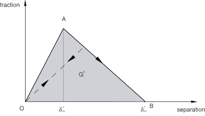
component involves specifying either the effective displacement at complete failure, , relative to the effective displacement at the initiation of damage, ; or the energy dissipated due to failure, (see Figure 3).
Figure 3. Linear damage evolution.
The second component to the definition of damage evolution is the specification of the
nature of the evolution of the damage variable, D, between initiation
of damage and final failure. This can be done by either defining linear or exponential
softening laws or specifying D directly as a tabular function of the
effective displacement relative to the effective displacement at damage initiation. The
material data described above will in general be functions of the mode mix, temperature,
and field variables.
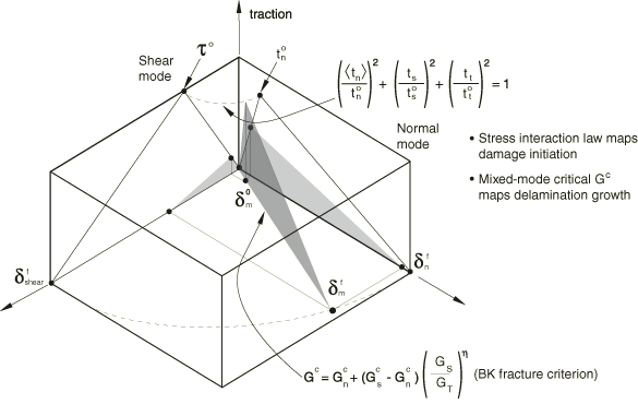
Figure 4 is a schematic representation of the dependence of damage initiation and evolution on
the mode mix, for a traction-separation response with isotropic shear behavior. The figure
shows the traction on the vertical axis and the magnitudes of the normal and the shear
separations along the two horizontal axes. The unshaded triangles in the two vertical
coordinate planes represent the response under pure normal and pure shear deformation,
respectively. All intermediate vertical planes (that contain the vertical axis) represent
the damage response under mixed mode conditions with different mode mixes. The dependence
of the damage evolution data on the mode mix can be defined either in tabular form or, in
the case of an energy-based definition, analytically. The manner in which the damage
evolution data are specified as a function of the mode mix is discussed later in this
section.
Figure 4. Illustration of mixed-mode response in cohesive elements.
Unloading subsequent to damage initiation is always assumed to occur linearly toward the
origin of the traction-separation plane, as shown in Figure 3. Reloading subsequent to unloading also occurs along the same linear path until the
softening envelope (line AB) is reached. Once the
softening envelope is reached, further reloading follows this envelope as indicated by the
arrow in Figure 3.
Evolution Based on Effective Displacement
You specify the quantity (that is, the effective displacement at complete failure, , relative to the effective displacement at damage initiation, , as shown in Figure 3) as a tabular function of the mode mix, temperature, and field variables. In addition,
you also choose either a linear or an exponential softening law that defines the detailed
evolution (between initiation and complete failure) of the damage variable,
D, as a function of the effective displacement beyond damage
initiation. Alternatively, instead of using linear or exponential softening, you can
specify the damage variable, D, directly as a tabular function of the
effective displacement after the initiation of damage, ; mode mix; temperature; and field variables.
Linear Damage Evolution
For linear softening (see Figure 3) Abaqus uses an evolution of the damage variable, D, that reduces (in
the case of damage evolution under a constant mode mix, temperature, and field
variables) to the expression proposed by Camanho and Davila (2002), namely:
In the preceding expression and in all later references, refers to the maximum value of the effective displacement attained
during the loading history. The assumption of a constant mode mix at a material point
between initiation of damage and final failure is customary for problems involving
monotonic damage (or monotonic fracture).
Input File Usage
Use the following option to specify linear damage evolution:
Property module: material editor: MechanicalDamage for Traction-Separation LawsQuade Damage, Maxe Damage, Quads Damage, or
Maxs Damage: SuboptionsDamage Evolution: Type:Displacement:
Softening:Linear
Exponential Damage Evolution
For exponential softening (see Figure 5) Abaqus uses an evolution of the damage variable, D, that reduces (in
the case of damage evolution under a constant mode mix, temperature, and field
variables) to
In the expression above is a nondimensional material parameter that defines the rate of damage
evolution and is the exponential function.
Figure 5. Exponential damage evolution.
Input File Usage
Use the following option to specify exponential softening:
Property module: material editor: MechanicalDamage for Traction-Separation LawsQuade Damage, Maxe Damage, Quads Damage, or
Maxs Damage: SuboptionsDamage Evolution: Type:Displacement:
Softening:Exponential
Tabular Damage Evolution
For tabular softening you define the evolution of D directly in
tabular form. D must be specified as a function of the effective
displacement relative to the effective displacement at initiation, mode mix,
temperature, and field variables.
Input File Usage
Use the following option to define the damage variable directly in tabular
form:
Property module: material editor: MechanicalDamage for Traction-Separation LawsQuade Damage, Maxe Damage, Quads Damage, or
Maxs Damage: SuboptionsDamage Evolution: Type:Displacement:
Softening:Tabular
Evolution Based on Energy
Damage evolution can be defined based on the energy that is dissipated as a result of the
damage process, also called the fracture energy. The fracture energy is equal to the area
under the traction-separation curve (see Figure 3). You specify the fracture energy as a material property and choose either a linear or
an exponential softening behavior. Abaqus ensures that the area under the linear or the exponential damaged response is equal to
the fracture energy.
The dependence of the fracture energy on the mode mix can be specified either directly in
tabular form or by using analytical forms as described below. When the analytical forms
are used, the mode mix ratio is assumed to be defined in terms of energies.
Tabular Form
The simplest way to define the dependence of the fracture energy is to specify it
directly as a function of the mode mix in tabular form.
Input File Usage
Use the following option to specify fracture energy as a function of the mode mix
in tabular form:
Property module: material editor: MechanicalDamage for Traction-Separation LawsQuade Damage, Maxe Damage, Quads Damage, or
Maxs Damage: SuboptionsDamage Evolution: Type:Energy: Mixed
mode behavior:Tabular
Power Law Form
The dependence of the fracture energy on the mode mix can be defined based on a power
law fracture criterion. The power law criterion states that failure under mixed-mode
conditions is governed by a power law interaction of the energies required to cause
failure in the individual (normal and two shear) modes. It is given by
The mixed-mode fracture energy when the above condition is satisfied. In other words,
You specify the quantities , , and , which refer to the critical fracture energies required to cause
failure in the normal, the first, and the second shear directions, respectively.
Input File Usage
Use the following option to define the fracture energy as a function of the mode
mix using the analytical power law fracture criterion:
Property module: material editor: MechanicalDamage for Traction-Separation LawsQuade Damage, Maxe Damage, Quads Damage, or
Maxs Damage: SuboptionsDamage Evolution: Type:Energy: Mixed
mode behavior:Power Law: Toggle on
Power and enter the exponent value
Benzeggagh-Kenane (BK)
Form
The Benzeggagh-Kenane fracture criterion (Benzeggagh and Kenane, 1996) is particularly
useful when the critical fracture energies during deformation purely along the first and
the second shear directions are the same; that is, . It is given by
where , , and is a material parameter. You specify , , and .
Input File Usage
Use the following option to define the fracture energy as a function of the mode
mix using the analytical BK
fracture criterion:
Property module: material editor: MechanicalDamage for Traction-Separation LawsQuade Damage, Maxe Damage, Quads Damage, or
Maxs Damage: SuboptionsDamage Evolution: Type:Energy: Mixed
mode behavior:Bk: Toggle on
Power and enter the exponent value
Linear Damage Evolution
For linear softening (see Figure 3) Abaqus uses an evolution of the damage variable, D, that reduces to
where with as the effective traction at damage initiation. refers to the maximum value of the effective displacement attained
during the loading history.
Input File Usage
Use the following option to specify linear damage evolution:
Property module: material editor: MechanicalDamage for Traction-Separation LawsQuade Damage, Maxe Damage, Quads Damage, or
Maxs Damage: SuboptionsDamage Evolution: Type:Energy:
Softening:Linear
Exponential Damage Evolution
For exponential softening Abaqus uses an evolution of the damage variable, D, that reduces to
In the expression above and are the effective traction and displacement, respectively. is the elastic energy at damage initiation. In this case the traction
might not drop immediately after damage initiation, which is different from what is seen
in Figure 5.
Input File Usage
Use the following option to specify exponential softening:
Property module: material editor: MechanicalDamage for Traction-Separation LawsQuade Damage, Maxe Damage, Quads Damage, or
Maxs Damage: SuboptionsDamage Evolution: Type:Energy:
Softening:Exponential
Defining Damage Evolution Data as a Tabular Function of Mode Mix
As discussed earlier, the material data defining the evolution of damage can be tabular
functions of the mode mix. The manner in which this dependence must be defined in Abaqus is outlined below for mode mix definitions based on energy and traction, respectively.
In the following discussion it is assumed that the evolution is defined in terms of
energy. Similar observations can also be made for evolution definitions based on effective
displacement.
Mode Mix Based on Energy
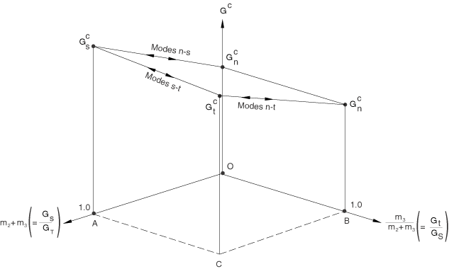
For an energy-based definition of mode mix, in the most general case of a
three-dimensional state of deformation with anisotropic shear behavior the fracture
energy, , must be defined as a function of and . The quantity is a measure of the fraction of the total deformation that is shear,
while is a measure of the fraction of the total shear deformation that is in
the second shear direction. Figure 6 shows a schematic of the fracture energy versus mode mix behavior.
Figure 6. Fracture energy as a function of mode mix.
The limiting cases of pure normal and pure shear deformations in the first and second
shear directions are denoted in Figure 6 by , , and , respectively. The lines labeled “Modes n-s,” “Modes n-t,” and “Modes
s-t” show the transition in behavior between the pure normal and the pure shear in the
first direction, pure normal and pure shear in the second direction, and pure shears in
the first and second directions, respectively. In general, must be specified as a function of at various fixed values of . In the discussion that follows we refer to a data set of versus corresponding to a fixed as a “data block.” The following guidelines are useful in defining the
fracture energy as a function of the mode mix:
For a two-dimensional problem needs to be defined as a function of ( in this case) only. The data column corresponding to must be left blank. Hence, essentially only one “data block” is
needed.
For a three-dimensional problem with isotropic shear response, the shear behavior
is defined by the sum and not by the individual values of and . Therefore, in this case a single “data block” (the “data block”
for ) also suffices to define the fracture energy as a function of the
mode mix.
In the most general case of three-dimensional problems with anisotropic shear
behavior, several “data blocks” would be needed. As discussed earlier, each “data
block” would contain versus at a fixed value of . In each “data block” can vary between 0 and . The case (the first data point in any “data block”), which corresponds to a
purely normal mode, can never be achieved when (that is, the only valid point on line
OB in Figure 6 is the point O, which corresponds to a purely
normal deformation). However, in the tabular definition of the fracture energy as a
function of mode mix, this point simply serves to set a limit that ensures a
continuous change in fracture energy as a purely normal state is approached from
various combinations of normal and shear deformations. Hence, the fracture energy of
the first data point in each “data block” must always be set equal to the fracture
energy in a purely normal mode of deformation ().
As an example of the anisotropic shear case, consider that you want to input three
“data blocks” corresponding to fixed values of 0., 0.2, and 1.0, respectively. For each of the three “data
blocks,” the first data point must be for the reasons discussed above. The rest of the data points in
each “data block” define the variation of the fracture energy with increasing
proportions of shear deformation.
Mode Mix Based on Traction
The fracture energy needs to be specified in tabular form of versus and . Thus, needs to be specified as a function of at various fixed values of . A “data block” in this case corresponds to a set of data for versus , at a fixed value of . In each “data block” can vary from 0 (purely normal deformation) to 1 (purely shear
deformation). An important restriction is that each data block must specify the same
value of the fracture energy for . This restriction ensures that the energy required for fracture as the
traction vector approaches the normal direction does not depend on the orientation of
the projection of the traction vector on the shear plane (see Figure 2).
Evaluating Damage When Multiple Criteria Are Active
When multiple damage initiation criteria and associated evolution definitions are used
for the same material, each evolution definition results in its own damage variable, , where the subscript i represents the
ith damage system. The overall damage variable,
D, is computed based on the individual , as explained in Evaluating Overall Damage When Multiple Criteria Are Active, for damage in
bulk materials.
Rate-Dependent Damage Evolution in Abaqus/Explicit
In Abaqus/Explicit you can define the damage evolution laws as a functions of the effective rate of
separation. You can combine this definition with rate-dependent damage initiation to
describe the rate-dependent delamination behavior for a cohesive interface.
Input File Usage
Use the following option to specify rate-dependent damage evolution:
Rate-dependent damage evolution is not supported in Abaqus/CAE.
Maximum Degradation and Choice of Element Removal
You have control over how Abaqus treats cohesive elements with severe damage. By default, the upper bound to the overall
damage variable at a material point is . You can reduce this upper bound as discussed in Controlling Element Deletion and Maximum Degradation for Materials with Damage Evolution. You can control
what happens to the cohesive element when the damage reaches this limit, as discussed below.
By default, once the overall damage variable reaches at all of its material points and none of its material points are in
compression, the cohesive elements, except for the pore pressure cohesive elements, are
removed (deleted). See Controlling Element Deletion and Maximum Degradation for Materials with Damage Evolution for details. This
element removal approach is often appropriate for modeling complete fracture of the bond and
separation of components. Once removed, cohesive elements offer no resistance to subsequent
penetration of the components, so it might be necessary to model contact between the
components as discussed in Defining Contact between Surrounding Components.
Alternatively, you can specify that a cohesive element should remain in the model even
after the overall damage variable reaches . In this case the stiffness of the element in tension and shear remains
constant (degraded by a factor of 1 − over the initial undamaged stiffness). This choice is appropriate if the
cohesive elements must resist interpenetration of the surrounding components even after they
have completely degraded in tension and shear (see Defining Contact between Surrounding Components). In Abaqus/Explicit it is recommended that you suppress bulk viscosity in the cohesive elements by setting
the scale factors for the linear and quadratic bulk viscosity parameters to zero using
section controls (see Section Controls).
Uncoupled Transverse Shear Response
An optional linear elastic transverse shear behavior can be defined to provide additional
stability to cohesive elements, particularly after damage has occurred. The transverse shear
behavior is assumed to be independent of the regular material response and does not undergo
any damage.
Transverse shear behavior is not supported in Abaqus/CAE for cohesive sections.
Viscous Regularization in Abaqus/Standard
Material models exhibiting softening behavior and stiffness degradation often lead to
severe convergence difficulties in implicit analysis programs, such as Abaqus/Standard. A common technique to overcome some of these convergence difficulties is the use of
viscous regularization of the constitutive equations, which causes the tangent stiffness
matrix of the softening material to be positive for sufficiently small time increments.
The traction-separation laws can be regularized in Abaqus/Standard using viscosity by permitting stresses to be outside the limits set by the
traction-separation law. The regularization process involves the use of a viscous stiffness
degradation variable, , which is defined by the evolution equation:
where is the viscosity parameter representing the relaxation time of the viscous
system and D is the degradation variable evaluated in the inviscid
backbone model. The damaged response of the viscous material is given as
The approximate amount of energy associated with viscous regularization over the whole
model or over an element set is available using output variable
ALLCD.
Equivalent nominal strain, (Abaqus/Explicit only). When the constitutive thickness of the cohesive layer is "artificially" set
as 1.0, the value of
NEEQ is equal to the value of the
effective displacement, .
NEEQR
Equivalent nominal strain rate, (Abaqus/Explicit only). When the constitutive thickness of the cohesive layer is "artificially" set
as 1.0, the value of
NEEQR is equal to the value of the
effective rate of separation, . The effective rate of separation is used to evaluate rate-dependent
damage initiation and evolution criteria.
STATUS
Status of element (the status of an element is 1.0 if the element is active, 0.0 if
the element is not).
SDEG
Overall value of the scalar damage variable, D.
DMICRT
All damage initiation criteria components.
MAXSCRT
Maximum value of the nominal stress damage initiation criterion at a material point
during the analysis. It is evaluated as
MAXECRT
Maximum value of the nominal strain damage initiation criterion at a material point
during the analysis. It is evaluated as
MMIXDME
Mode mix ratio during damage evolution. If the energy-based mode mix is used, it is
evaluated as ; if the traction-based mode mix is used, it is evaluated as . In general, it varies with time at a given integration point. This
variable is set to before initiation of damage.
MMIXDMI
Mode mix ratio at damage initiation. It is evaluated at the time of damage initiation
at an integration point for the very first time as if the energy-based mode mix is used; otherwise, if the
traction-based mode mix is used, it is evaluated as . Following damage initiation, it remains constant with time at a
given integration point. This variable is set to before initiation of damage.
QUADSCRT
Maximum value of the quadratic nominal stress damage initiation criterion at a
material point during the analysis. It is evaluated as
QUADECRT
Maximum value of the quadratic nominal strain damage initiation criterion at a
material point during the analysis. It is evaluated as
ALLCD
The approximate amount of energy over the whole model or over an element set that is
associated with viscous regularization in Abaqus/Standard. Corresponding output variables (such as
CENER,
ELCD, and
ECDDEN) represent the energy
associated with viscous regularization at the integration point level and element
level (the last quantity represents the energy per unit volume in the element),
respectively.
For the variables above that indicate whether a certain damage initiation criterion has
been satisfied or not, a value that is less than 1.0 indicates that the criterion has not
been satisfied, while a value of 1.0 or higher indicates that the criterion has been
satisfied. If damage evolution is specified for this criterion, the maximum value of this
variable does not exceed 1.0. However, if damage evolution is not specified for the
initiation criterion, this variable can have values higher than 1.0. The extent to which the
variable is higher than 1.0 can be considered to be a measure of the extent to which this
criterion has been violated.
References
Benzeggagh, M.L., and M. Kenane, “Measurement
of Mixed-Mode Delamination Fracture Toughness of Unidirectional Glass/Epoxy
Composites with Mixed-Mode Bending
Apparatus,” Composites Science and
Technology, vol. 56, pp. 439–449, 1996.
Camanho, P.P., and C. G. Davila, “Mixed-Mode
Decohesion Finite Elements for the Simulation of Delamination in Composite
Materials,” NASA/TM-2002–211737, pp. 1–37, 2002.