Beam-based submodeling imposes the displacements and rotations obtained from the
beam elements in the global model onto a surface representing the beam cross-section in
the submodel. The beam in the submodel is meshed with either solid or shell
elements.
Beam-based submodeling enables a strategy to use beam elements in a global model to
obtain an approximate solution efficiently followed by a submodel with solid or
shell elements to study a region in more detail. Results from the global model
impose conditions on cut surfaces of the submodel.
Invoking Beam-Based Submodeling
Creating and executing a submodel in the context of beam-based submodeling involves
the following:
Named surfaces that will be associated with submodel cuts must be specified as
model data.
Conditions at driven submodel cuts are specified with submodel cut definitions
within the context of an overall submodel conditions definition.
Data that is common to all submodel cuts, such as the associated step and
increment of the global model, is specified as part of the submodel conditions
definition for a step.
The name of the associated global model is specified with the
globalmodel parameter on the Abaqus command line.
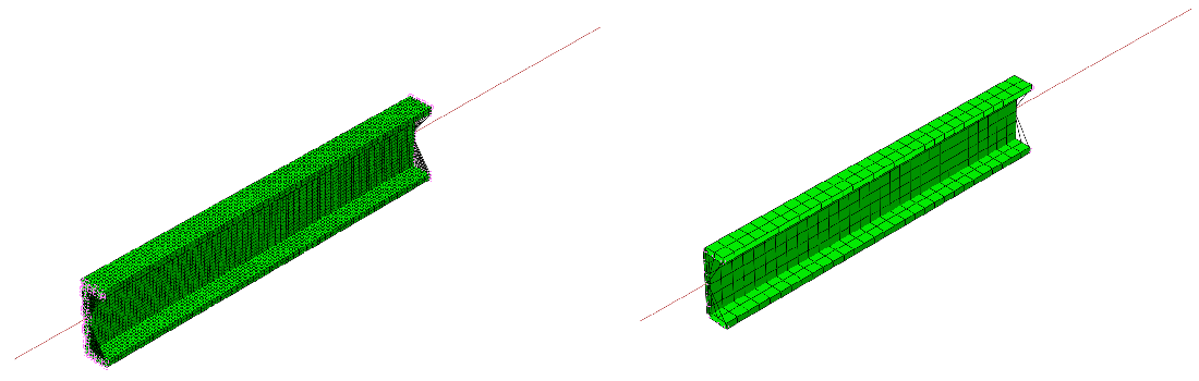
Beam-based submodeling in Abaqus/Standard imposes boundary conditions on primary degrees of freedom of a submodel based on
results from the global model with beam elements. Figure 1 shows
superimposed global and local models for beam-to-solid and beam-to-shell submodeling
examples. Abaqus/Standard internally generates a distributing coupling with the nodes on cut surfaces
acting as cloud nodes. These distributing couplings are represented with lines from
the reference node to each of the cloud nodes at the four submodel cuts in Figure 1. Reference
nodes for these distributing couplings are located at the intersection of the plane
of the cut surface and the beam element reference line in the global model. Abaqus/Standard obtains the values of the imposed degrees of freedom at the reference node in the
submodel by interpolation from the global model solution for the beam element at the
location of the intersection. The distributing coupling causes the average
displacement and rotation of the cut surface to match that of the reference node,
without imposing rigidity. For example, the distributing coupling does not prevent
warping of the cut surface during the submodel simulation. Figure 1. Superimposed global and local models for beam-to-solid (left) and
beam-to-shell (right) submodeling.
Consistent Configuration and Orientation
Accurate beam-based submodel behavior for beam-based submodeling requires consistency
of the beam cross-section configuration in the global and local models. Initial
nodal positions of the local submodel must account for:
Beam section offset in the global model
The orientation of principal beam axes in the global model
Beam section dimensions and thicknesses
Referring to the Step and Increment of the Global Model
You must provide the step number from the global model whose solution you would like
to use to impose the submodel conditions. If the submodel analysis step is a
perturbation step that refers to a general step in the global analysis, you must
also provide the increment number within the general step.
The time period for the global model step and the submodel might differ, especially
when one of the models is dynamic and the other is quasi-static. You can scale the
time in the global model such that it will match the time period in the submodel.
You can also scale the amplitude of the global model solution.
Controls Associated with Identifying the Global Element Associated with a Cut
Surface
A search algorithm identifies the global beam element associated with each local cut
surface. The default search algorithm usually does not require user control.
Optionally, you can specify a global element set as input to this algorithm to limit
which global elements are considered as candidates. If a cut surface of the local
model corresponds to the location of a node shared by multiple beam elements in the
global model, specifying one of these elements in a global element set will remove
uncertainty in which global element is chosen to drive the submodel conditions at
that cut. Similarly, you can define tolerances to include or exclude entities that
lie outside the boundaries of the submodel. You can specify the tolerances either as
a percentage of the average element size or as absolute values.
Limiting Imposed Conditions to Certain Degrees of Freedom at a Submodel Cut
By default, Abaqus/Standard assumes that all available primary degrees of freedom are being imposed based on
results of the global model at a submodel cut. However, you can selectively choose
which degrees of freedom to impose, or you can exempt a specific degree of freedom.
You can modify the imposed conditions across the steps.
Input File Usage
Use following option to choose which degrees of freedom are imposed:
SUBMODEL CUT, MAIN IMPOSED CONDITIONS=PRIMARY, OP=MODorNEWdegree of freedom, PRIMARY, degree of freedom, PRIMARY
Use following option to exempt a specific degree of freedom:
SUBMODEL CUT, MAIN IMPOSED CONDITIONS=NONE, OP=MODorNEWdegree of freedom, PRIMARY, degree of freedom, PRIMdegree of freedom, NONE, degree of freedom, NONE
Output
Submodel analysis is identical to any other analysis. You can request all output
variables that are appropriate to the procedure.
Limitations
The following limitations apply to beam-based submodeling:
Beam-based submodeling is not available for plane strain, plane stress, or
axisymmetric models.
Restart of a beam-based submodel analysis is not supported.