About Mesh Smoothing (MESH_SMOOTH) | |||||||
|
| ||||||
For shape optimization with Tosca Structure,
the existing inner mesh is automatically adjusted to the surface displacement after the
determination of the surface modification. No remeshing of the model is carried out, but the
displacement of the surface nodes is passed on to the inner nodes. This modified mesh is then
used as the basis of the FE calculations that follow. The parameters for mesh smoothing are
specified with the MESH_SMOOTH command.
The most important parameter is to define the area to which the mesh correction is applied. Default values for other settings are such that satisfactory results can be achieved for most models. The most important additional options are
FREE_SF, LEVEL_QUAL, SOLVER_CHECK/SOLVER_STOP,
and STRATEGY
and are described in the following chapters.
| Important: It is strongly recommended for the start model of the shape optimization to have a finite element mesh of good quality. This recommendation especially applies to areas in which shape changes are expected. |
Element Group for Mesh Smoothing
The area to which mesh smoothing is applied to is defined by an element group. This element group must contain all design nodes.
 |
- The operation for mesh smoothing can require a great deal of computing time depending on the selected options. It is therefore advisable to select an area for the mesh smoothing that is sufficient but not too large. The size of the area for mesh smoothing depends on the problem and must be specified by the user.
- Mesh smoothing is an element-based algorithm; that is, the
MESH_SMOOTHarea is processed element by element. For FE models with relatively numerous elements in relation to the number of degrees of freedom (tetrahedral mesh), the computing time of the optimization module can sharply increase in comparison to the computing time of the FE analysis.
Important:
|
| Warning:
All nodes in the |
- In general, it is possible to use a default
MESH_SMOOTHarea consisting of 6 layers of elements around the design nodes. However, this method is not recommended because the user looses control of which nodes might be moved byMESH_SMOOTH. Thus, it is recommended to choose an element group (for example, in a preprocessor) to avoid unwanted effects. - It is possible to limit the optimization displacements of the design
nodes and the displacements of the
MESH_SMOOTHnodes using design variable constraints (DVCON_SHAPEdefinitions).
For each mesh smooth definition, several groups are created automatically by Tosca Structure. Some are available directly after the preprocessing of the MESH_SMOOTH
definition and are thus available for other definitions (for example, constraints) further on.
name of the group |
description |
|---|---|
LAYER_<mesh_smooth_name> |
created, if MS_LAYER is used; contains all elements of the mesh smooth area |
<mesh_smooth_name>_ELEM |
created, if the user-defined element group contains disallowed elements; contains all allowed elements (TRIA, QUAD, TETRA, HEXA, and PENTA) |
<mesh_smooth_name>_NODE |
contains all nodes attached to the allowed elements of the MESH_SMOOTH element group |
<mesh_smooth_name>_SF_ELEM |
contains all allowed elements of the MESH_SMOOTH element group with at least one surface node |
Others are created when the definition of the optimization task is completed and read into the Tosca Structure database.
name of the group |
description |
|---|---|
<mesh_smooth_name>_SF_NODE |
contains all mesh smooth nodes at the surface of the mesh |
<mesh_smooth_name>_DV_ELEM |
contains all allowed elements of the MESH_SMOOTH element group with at least one design node |
<mesh_smooth_name>_DL_NODE |
contains all mesh smooth nodes that are also design nodes or nodes restricted with a LINK_SHAPE |
<mesh_smooth_name>_DL_ELEM |
contains all elements with at least one node out of <mesh_smooth_name>_DL_NODE |
<mesh_smooth_name>_SF |
contains all mesh smooth nodes that are automatically fixed |
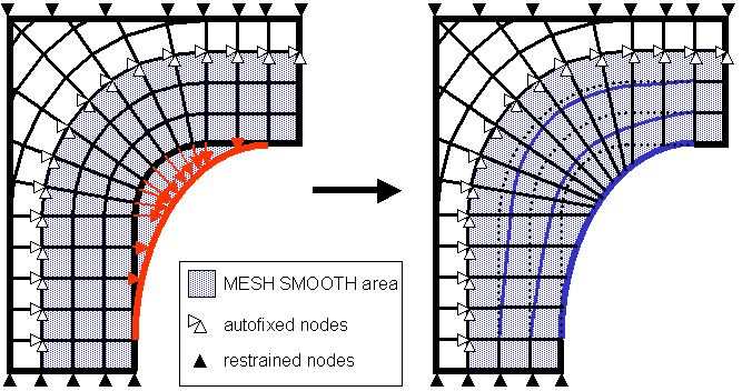
Fixation of Free Surface Nodes (FREE_SF)
In the following figure, transition nodes are pictured for a) FREE_SF=FIX,0
and b) FREE_SF=FREE. The MESH_SMOOTH area contains
design nodes, surface nodes that are not design nodes and inner nodes.
In many cases, it is desirable to adjust the surface nodes (in proximity of the design nodes) in the mesh smoothing to achieve a smooth transition between the design area and remaining area. However, in other cases, it makes more sense to fix the surface nodes to avoid an unwanted displacement of the nodes by the mesh smoothing.
For example, the front side of a
component is the design area. The MESH_SMOOTH area extends
over the entire component. If the back side of the component is to remain
unchanged, the surface nodes on the back side must be fixed. The FREE_SF=FIX
setting enables free surface nodes to be fixed automatically in all displacement
directions during the mesh smoothing:
MESH_SMOOTH
 ...
 FREE_SF = FIX, <number_of_node_layers>
END_
All surface nodes of the MESH_SMOOTH area that are neither design nodes nor
limited by restrictions are interpreted as free surface nodes. FREE_SF=FIX,0 is
set by default; the free surface nodes cannot be moved during mesh smoothing.
The FREE_SF=FIX setting can also be modified by specifying a number of node
layers (layers field next to FREE_SF choice menu, default=0);
for example, FREE_SF=FIX,5. This number of node layers specifies how many node layers,
beginning with the design nodes along the surface, should remain free and not be fixed. This
enables the transition area in vicinity of the design area to be kept free despite the fixed
surface. Node layers consisting of midside nodes are not taken into consideration, only node
layers consisting of corner nodes.
Important:
|
Fixation of the MESH_SMOOTH Area Boundary
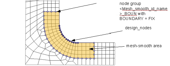 |
The boundary between area and the remaining model is fixed per default
as the mesh smoothing should stay restricted to the area defined for
this purpose (BOUNDARY = FIX parameter). The nodes
on the boundary are internally stored in a node group with the name
<Mesh_smooth_id_name>_BOUN.
If in some cases you might not want all "border" nodes to be fixed,
you can select the BOUNDARY = FREE option. Then you
are responsible to fix the proper nodes by yourself with DVCON_SHAPE
entries.
Automatic MESH_SMOOTH Area (MS_LAYER)
The area for mesh smoothing should be as small as possible but as large as required. The element
group ALL_ELEMENTS should not be used for smoothing if only a small
part of the model should be optimized. The calculation time of the optimization
module increases and all free surface nodes must be fixed explicitly by the user.
The MESH_SMOOTH parameter MS_LAYER allows the automatic
definition of a mesh smooth element group consisting of a certain number of element layers with
reference to a node group. In
Tosca Structure.gui,
it is chosen by switching the radio button for the mesh smooth area to ND_GROUP,
LAYER in and choosing group and number correspondingly.
Example
Starting at the design node group, a mesh smooth domain is generated with 5 element layers:
MESH_SMOOTH
 ID_NAME  = new_mesh_smooth
 MS_LAYER = design_nodes, 5
 FREE_SF  = FIX, 3
END_
In Tosca Structure.gui, the definition looks as follows:
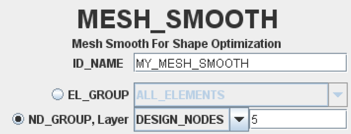 |
Convergence of the Smoothed Mesh (LEVEL_CONV)
The algorithms for mesh smoothing are iterative; the mesh smoothing is performed in several
successive steps. The decisive factor for the convergence of the smoothed mesh is the number of
steps in combination with the increments. The iterative process can be influenced using the
convergence parameter, LEVEL_CONV. The default setting is
LEVEL_CONV=LOW; only a few iterations with large increments are
performed. This is the most efficient setting. The convergence behavior can be improved with the
settings LEVEL_CONV=MEDIUM and LEVEL_CONV=HIGH. These settings
result in increasingly more iterations with smaller increments to be performed which, however,
can result in a substantial increase in the computing time required. The goal should always be
to work with the lowest possible convergence parameter to avoid unnecessarily long computing
times.
MESH_SMOOTH
 ...
 LEVEL_CONV = LOW
END_
| Important:
You should adjust the setting of the The |
Enforcing Restrictions (LEVEL_DVCON)
The mesh smoothing algorithm consists of several subalgorithms that are executed consecutively.
The displacement of the MESH_SMOOTH nodes can be restricted by
DVCON_SHAPE entries (declared with OPTIMIZE). The
LEVEL_DVCON setting can be used to control the enforcement of the
DVCON_SHAPE entries in the individual subalgorithms for the mesh smoothing.
LEVEL_DVCON=LOW is set by default; the DVCON_SHAPE
entries for mesh smoothing are forced. This is the most efficient setting. The settings
LEVEL_DVCON=MEDIUM and LEVEL_DVCON=HIGH causes the
DVCON_SHAPE entries to be forced more often. The goal is to work with the
lowest parameter value possible to avoid unnecessarily long computing times.
MESH_SMOOTH
 ...
 LEVEL_DVCON = LOW
END_
Quality Control and Improvement (LEVEL_QUAL)
Mesh smoothing attempts to improve the quality of the mesh despite the mesh distortion that
results from the optimization displacement of the design nodes. The mesh quality can
be controlled using the LEVEL_QUAL parameter. The value
LEVEL_QUAL=LOW is set by default; improvement of the mesh
quality is attempted during the mesh smoothing. This is the most efficient setting.
Generally, an increase to LEVEL_QUAL=MEDIUM or
LEVEL_QUAL=HIGH leads to further improvement of the mesh
quality but at the cost of increased computing time. The subalgorithm can be
deactivated by setting LEVEL_QUAL=NOT.
Mesh smoothing attempts to improve the quality of the mesh despite the mesh distortion that
results from the optimization displacement of the design nodes. The mesh quality can be
controlled using the LEVEL_QUAL parameter. The value
LEVEL_QUAL=LOW is set by default; improvement of the mesh quality is
attempted during the mesh smoothing. This is the most efficient setting. Generally, an increase
to LEVEL_QUAL=MEDIUM or LEVEL_QUAL=HIGH leads to further
improvement of the mesh quality but at the cost of increased computing time. The subalgorithm
can be deactivated by setting LEVEL_QUAL=NOT.
MESH_SMOOTH
 ...
 LEVEL_QUAL = LOW
END_
Important:
|
Quality parameters
The quality values of the sub algorithm mentioned are determined for each element and base on the
angle quality and, for tetrahedral elements, the quality of the aspect ratio. The quality value
lies between 1 (best element quality) and 0 (poorest element quality). The poorest quality value
of an angle or aspect ratio is always decisive for the element. The user can specify the
interval limit (*_LOW_*, *_HIGH_*) outside of which the elements are rated as
poor by the quality algorithm. The poorer an element is rated, the greater the consideration it
is given in improving the element quality.
MESH_SMOOTH
 ...
 QUAD_LOW_ANGLE    = <value>
 QUAD_HIGH_ANGLE   = <value>
 TRIA_LOW_ANGLE    = <value>
 TRIA_HIGH_ANGLE   = <value>
 TETRA_LOW_ASPECT  = <value>
 TETRA_HIGH_ASPECT = value>
END_
The way the quality values are determined can be outlined as follows:
QUADplanes (QUADelements, lateral planes ofHEXAandPENTAelements):- Optimum angle is
90°-> quality=1. - Angle smaller or equal to
QUAD_LOW_ANGLE -> quality=0. - Angle greater or equal to
QUAD_HIGH_ANGLE -> quality=0.
- Optimum angle is
TRIAsurfaces (TRIAelements, lateral surfaces ofTETRAandPENTAelements):- Optimum angle is
60° -> quality=1. - Angle smaller or equal to
TRIA_LOW_ANGLE -> quality=0. - Angle greater or equal to
TRIA_HIGH_ANGLE -> quality=0.
- Optimum angle is
TETRAelements:- Optimum aspect ratio is 1.33 ->
quality=1. - Aspect ratio smaller or equal to
TETRA_LOW_ASPECT -> quality=0. - Aspect ratio greater or equal to
TETRA_HIGH_ASPECT -> quality=0.
- Optimum aspect ratio is 1.33 ->
Important:
|
Poor Quality Elements
A list of the elements that are rated as poor quality by MESH_SMOOTH with an
internal quality value of zero can be made as an output. To do so, set the
QUAL_LIST=YES parameter. The default setting is QUAL_LIST=NO,
and no list of poor quality elements is printed out.
MESH_SMOOTH
 ...
 QUAL_LIST = NO
END_
The list of poor quality elements can only be printed for LEVEL_QUAL=LOW,
MEDIUM or HIGH. No element qualities are calculated
with LEVEL_QUAL=NOT and poor elements cannot be identified.
Quality Criteria of the Solver (SOLVER_CHECK)
In shape optimization, there is a danger that the required optimum cannot be achieved with the specified mesh that is continually adjusted to changing conditions. This means that the mesh is a component that should be restricted in the optimization job. Usually, the quality of the mesh decreases with an increase in the number of design cycles.
Therefore, the program for the finite element analysis might stop. Some quality criteria for elements are checked in the finite element analysis program. If the solver identifies elements that are too poor in quality, the finite elements analysis is stopped. This has the disadvantage that no analysis results for the subsequent design cycle are then available in Tosca Structure and therefore, the optimization must be stopped (error message because of lack of results data instead of error message because of poor mesh quality).
Using the option SOLVER_CHECK=YES (default is NO)
the user has the possibility, to check some finite element solver quality
criteria in the Tosca Structure
optimization module before the actual finite elements analysis. The quality
criteria Q4TAPER, Q4SKEW, T3SKEW and TETRAAR
are checked. The poorest values and the corresponding elements are logged
to the output file. The default values in Tosca Structure
can be changed by the user using the options Q4TAPER, Q4SKEW,
T3SKEW and TETRAAR. The option SOLVER_STOP=YES
(default is NO) causes a regular program stops in the
Tosca Structure
optimization module when one of the quality criteria is violated. This
means that the subsequent finite elements analysis, which would be canceled
without results data, is no longer carried out. This setting has the
advantage that an optimization stop is easier to understand for the user
who does not need to check the finite element solver result files
for the source of the error anymore.
MESH_SMOOTH
...
SOLVER_CHECK = YES
Q4TAPER      = <value>
Q4SKEW       = <value>
T3SKEW       = <value>
TETRAAR      = <value>
SOLVER_STOP  = YES
END_
Important:
|
Modification of Design Nodes (FREEZE_DESIGN_NODES)
Especially the CONSTRAINED_LAPLACIAN mesh smoothing algorithm performs
improvements on the mesh surface. This implies that design nodes are moved as well. In
sensitivity-based shape optimizations with manufacturing constraints, the mesh smoothing module
can overrule the manufacturing constraint. For this reason, it is possible to exclude the design
nodes from mesh smoothing; the mesh smoothing module does not modify the design nodes.
MESH_SMOOTH
 ID_NAME             = MY_MESHSMOOTH
 ...
 FREEZE_DESIGN_NODES = YES | NO
END_
Correction of Distorted Elements (CORRECT_ELEMENTS)
In some cases, the program for the finite element analysis stops because of bad element quality (inverted element or aspect ratio too big) some time during the optimization and thus prevents Tosca Structure from performing the optimization task. Very often only a few elements cause this issue and the required optimum is only slightly affected when modifying the concerned elements to gain a better mesh quality.
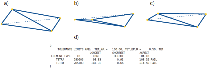
The above figure explains the correction of distorted elements: a) Original element, b) Optimized element with bad aspect ratio (d), c) Corrected element (good aspect ratio).
The element correction feature can be activated with the CORRECT_ELEMENTS = YES option
(default, use NO to disable) for all supported element types.
For elements with bad element quality, it is tried to correct the element
CE_CORRECTION_LOOPS times by multiplying the optimization displacements with
CE_CORRECTION_FACTOR (default is 0.5). If the element is still in a poor
state, it depends on CE_FAIL_ACTION what is done next:
If CE_FAIL_ACTION = RESET is set (default), the optimization displacement is set
to zero.
If CE_FAIL_ACTION is set to CONTINUE the element is
left as it is (with the risk that the solver stops).
MESH_SMOOTH
 ...
 TETRAAR              = <value>
 CORRECT_ELEMENTS     = YES | NO
 CE_CORRECTION_LOOPS  = <int value>
 CE_CORRECTION_FACTOR = <value> (0.5)
 CE_FAIL_ACTION       = RESET | CONTINUE
END_
Important:
|
Mesh Smooth Strategy (STRATEGY)
The mesh smooth strategy is defined by the parameter STRATEGY. By
default, STRATEGY = CONSTRAINED_LAPLACIAN, and the default
mesh smoothing method is used. If, instead, STRATEGY = LOCAL_GRADIENT
is chosen, the optimization-based mesh smoothing algorithm is used. In
each iteration, it identifies the elements with the worst element quality
and improves them by displacing the nodes. For relatively small models
(less than 1000 nodes in the mesh smooth area), the method usually results
in meshes with elements having the optimal shape; the measure of the
optimality is roughly the ratio of the element volume (area for shell
elements) to the corresponding power of its diameter. For larger models,
the iterations tend to stop before the optimal mesh quality is reached
since otherwise the calculation time becomes too large. In this case,
the changes might only affect the elements with the worst element quality.
The nodes on the surface are displaced as well, though their displacements
are chosen to be parallel to the surface. It guarantees that the overall
geometry remains mostly unchanged by the algorithm.
level_conv and level_dvcon
parameters are not used if STRATEGY = LOCAL_GRADIENT
is specified.Using STRATEGY = EXTERNAL, you can use separate mesh smoother algorithms
during the optimization, e.g. with the CST solver.
The mesh corrections are read from an additional, by default optional, file defined using the command item
FILE.
MESH_SMOOTH
    ID_NAME   = MY_EXT_MESHSMOOTH
    STRATEGY  = EXTERNAL
    FILE_NAME = delta_mesh.onf
END_