Elements tested
CPE4R
C3D8R
M3D4R
S4R
ProductsAbaqus/Explicit Elements testedCPE4R C3D8R M3D4R S4R Features testedLarge deformation kinematics, elastic-plastic material with strain hardening, user material, multi-point constraints. Problem descriptionThe rotating cylinder problem was proposed by Longcope and Key (1977) as a means of exercising finite rotation algorithms. In this problem a cylinder with an initial angular velocity of 4000 rad/sec and a zero initial stress state is modeled. (This is physically impossible because the body forces would generate a stress field under this angular velocity. Nevertheless, these initial conditions are acceptable, since this is merely a numerical experiment.) The inside of the cylinder is subjected to an instantaneous application of a pressure of 67.3 MPa (9760 psi). The elastic material properties are defined as Young's modulus of 71 GPa (1.03 × 10⁷ psi), Poisson's ratio of 0.3333, and density of 2680 kg/m3 (2.508 × 10⁻⁴ lb sec2 in−4). An isotropic hardening plasticity model is used with an initial yield of 286 MPa (4.15 × 10⁴ psi) and constant hardening modulus of 3.565 GPa (5.17 × 10⁵ psi). Only one-quarter of the ring is modeled using a constraint equation and a multi-point constraint to enforce the repeated symmetry boundary condition. A local cylindrical coordinate system is defined at each material point of the mesh. Results and discussionThe first case considered is a two-dimensional model using CPE4R elements. In this case two meshes are defined in the same problem, as shown in Figure 1. The lower mesh in Figure 1 uses the built-in Mises isotropic hardening plasticity model. The upper mesh in Figure 1 employs user subroutine VUMAT with the kinematic hardening Mises model described in Models for Metals Subjected to Cyclic Loading. Figure 2 shows the time history of the maximum principal stress in the two-dimensional model for both cases. Figure 3 shows the time history of equivalent plastic strain in the two-dimensional model for both cases. Figure 4 shows the energy histories in the two-dimensional model. The energy history is particularly important in this analysis because it demonstrates that there is no energy lost in the enforcement of multi-point constraints. The second case is a three-dimensional representation of the same problem using shells, membranes, and brick elements to model the ring with suitable boundary conditions to reproduce closely the original two-dimensional model. The built-in Mises isotropic hardening plasticity model is used. The meshes for the three-dimensional case are shown in Figure 5. Figure 6 shows the time history of the maximum principal stress in the three-dimensional model for both cases. Figure 7 shows the time history of the equivalent plastic strain in the three-dimensional model for both cases. Figure 8 shows the energy histories in the three-dimensional model. Note that each energy quantity is summed over the two cases. The results compare well with those obtained by Longcope and Key (1977). Input files
References
Figures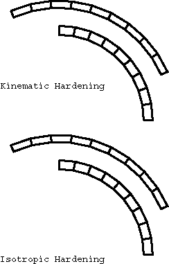 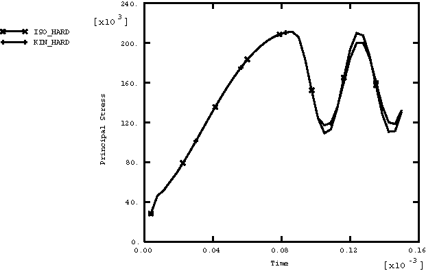 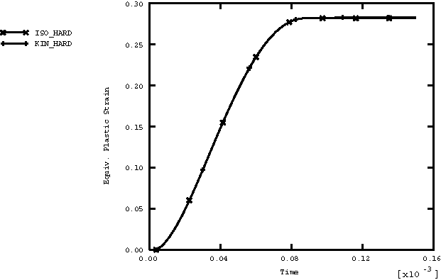 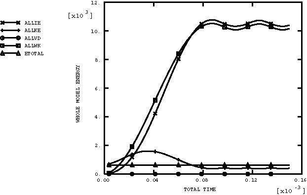 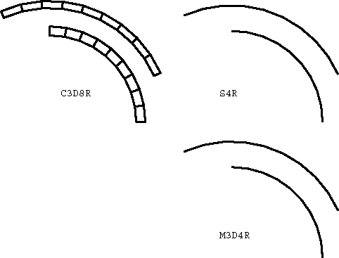 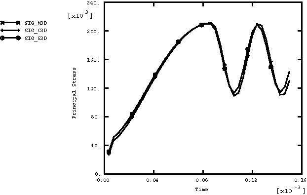 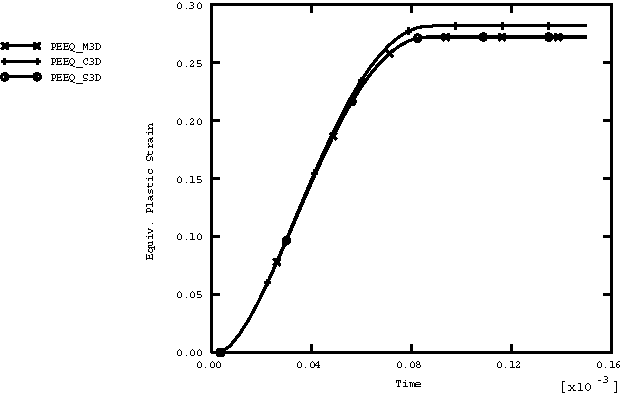 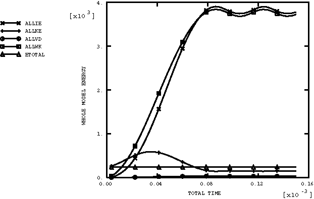 | |||||||