*TRANSFORM | ||||||
|
| |||||
ProductsAbaqus/StandardAbaqus/ExplicitAbaqus/CAE
TypeModel data
LevelPartPart instanceAssembly
Abaqus/CAEDefine nodal coordinate systems for prescribed conditions in the Load module.
Required parameters
- NSET
-
Set this parameter equal to the name of the node set for which the local transformed system is being given.
Optional parameters
Data line to define a transformed coordinate system
- First (and only) line
-
-
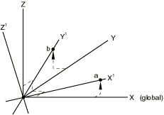
Global X-coordinate of point a specifying transformation.
-
Global Y-coordinate of point a specifying transformation.
-
Global Z-coordinate of point a specifying transformation.
-
Global X-coordinate of point b specifying transformation.
-
Global Y-coordinate of point b specifying transformation.
-
Global Z-coordinate of point b specifying transformation.
-


