Prescribing boundary conditions and applied loads

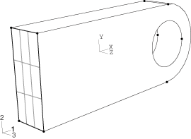
In this model the left-hand end of the connecting lug needs to be constrained in all three directions. This region is where the lug is attached to its parent structure (see Figure 1). In Abaqus/CAE boundary conditions are applied to geometric regions of a part rather than to the finite element mesh itself. This association between boundary conditions and part geometry makes it very easy to vary the mesh without having to respecify the boundary conditions. The same holds true for load definitions.

This task shows you how to:

Context:

Figure 1. Built-in end of the connecting lug.

The lug carries a pressure of 50 MPa distributed around the bottom half of the hole. To apply the load correctly, however, the part must first be partitioned (i.e., divided) so that the hole is composed of two regions: a top half and a bottom half.

You use the Partition toolset to divide a part or assembly into regions. Partitioning is used for many reasons; it is commonly used for the purposes of defining material boundaries, indicating the location of loads and constraints (as in this example), and refining the mesh. An example of the use of partitioning for meshing purposes is discussed in the next section. For more information on partitioning, see The Partition toolset.

Dependent part instances cannot be modified at the assembly level (e.g., they cannot be partitioned in an assembly-level module). The reason for this restriction is that all dependent instances of a part must have identical geometry so they can share the same mesh topology as the original part. Thus, any change to a dependent part instance has to be made to the original part itself (i.e., at the part level). In contrast, independent part instances may be partitioned at the assembly level. In this example a dependent part instance (the default) was created; the corresponding partitioning instructions follow.

Prescribe boundary conditions

  1. In the Model Tree, double-click the BCs container to prescribe boundary conditions on the model. In the Create Boundary Condition dialog box that appears, name the boundary condition Fix left end, and select LugLoad as the step in which it will be applied (since it is a fixed condition, it can be applied either in the initial step or the analysis step; here we choose the analysis step for convenience). Accept Mechanical as the category and Symmetry/Antisymmetry/Encastre as the type. Click Continue.
  2. You may need to rotate the view to facilitate your selection in the following steps. Select ViewRotate from the main menu bar (or use the tool from the View Manipulation toolbar) and drag the cursor over the virtual trackball in the viewport. The view rotates interactively; try dragging the cursor inside and outside the virtual trackball to see the difference in behavior. Click mouse button 2 to exit the rotate view tool before proceeding.
  3. Select the left end of the lug (indicated in Figure 1) using the cursor. Click Done in the prompt area when the appropriate region is highlighted in the viewport, and toggle on ENCASTRE in the Edit Boundary Condition dialog box that appears. Click OK to apply the boundary condition.

    Arrows appear on the face indicating the constrained degrees of freedom. The encastre boundary condition constrains all active structural degrees of freedom in the region specified; after the part is meshed and the job is created, this constraint will be applied to all the nodes that occupy the region.
Partition a dependent part instance

  1. In the Model Tree, double-click the Lug item in the Parts container to make it current.
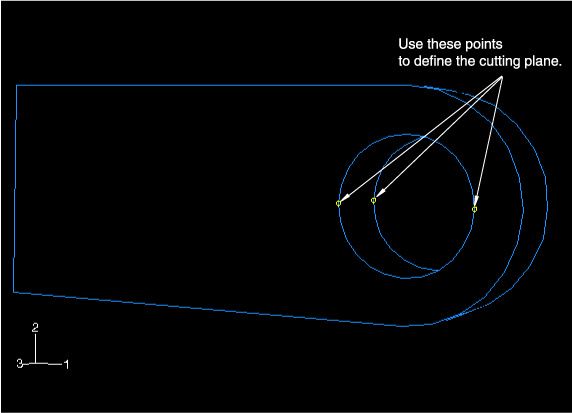
  2. Use the Partition Cell: Define Cutting Plane tool to divide the part in half. Use the 3 Points method to define the cutting plane. When you are prompted to select a point, Abaqus/CAE highlights the points you can select: vertices, datum points, edge midpoints, or arc centers. In this model the points used to define the cutting plane are indicated in Figure 2. Again, you may need to rotate the view to facilitate your selection.

    Figure 2. Points used to define the cutting plane.

  3. Click Create Partition in the prompt area after you have finished selecting the points.

Apply a pressure load

  1. In the Model Tree, double-click the Loads container to prescribe the pressure load. In the Create Load dialog box that appears, name the load Pressure load and select LugLoad as the step in which it will be applied. Select Mechanical as the category and Pressure as the type. Click Continue.
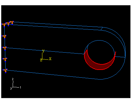
  2. Select the surface associated with the bottom half of the hole using the cursor; the region is highlighted in Figure 3. When the appropriate surface is selected, click Done in the prompt area.

    Figure 3. Surface to which pressure will be applied.

  3. Specify a uniform pressure of 5.0E7 in the Edit Load dialog box, accept the default Amplitude, and click OK to apply the load.

    Arrows appear on the bottom half of the hole indicating the applied load.