Defining the material and section properties and the local material directions

The plate is made of an isotropic, linear elastic material with a Young's modulus E = 30 × 109 Pa and a Poisson's ratio ν = 0.3.

Context:

Create the material definition; name the material Metal.

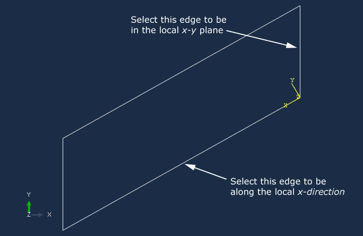
The orientation of the structure in the global coordinate system is shown in Figure 1. The global Cartesian coordinate system defines the default material directions, but the plate is skewed relative to this system. It will not be easy to interpret the results of the simulation if you use the default material directions because the direct stress in the material 1-direction, σ11, will contain contributions from both the axial stress, produced by the bending of the plate, and the stress transverse to the axis of the plate. It will be easier to interpret the results if the material directions are aligned with the axis of the plate and the transverse direction. Therefore, a local rectangular coordinate system is needed in which the local x-direction lies along the axis of the plate (i.e., at 30° to the global 1-axis) and the local y-direction is also in the plane of the plate. Following the instructions given below, define the shell section properties in a local (nondefault) material coordinate system.

  1. Define a homogeneous shell section named PlateSection. Specify that section integration be performed before the analysis since the material is linear elastic, and accept the default idealization option of No idealization. Assign a shell thickness of 0.8E-2 and the Metal material definition to the section.
  2. Define a rectangular datum coordinate system as shown in Figure 1 using the Create Datum CSYS: 2 Lines tool .

    Figure 1. Datum coordinate system used to define local material directions.

  3. From the main menu bar of the Property module, select AssignMaterial Orientation and select the entire part as the region to which local material directions will be applied. In the viewport, select the datum coordinate system created earlier. Select Axis 3 for the direction of the approximate shell normal. No additional rotation is needed about this axis.

    Tip: To verify that the local material directions have been assigned correctly, select ToolsQuery from the main menu bar and perform a property query on the material orientations. Triads appear in the viewport indicating the material orientation of the region you select.

    Once the part has been meshed and elements have been created in the model, all element variables will be defined in this local coordinate system.

  4. Assign the section definition to the plate. Accept Middle surface as the shell offset definition.