Defining beam section properties | ||
| ||
Context:
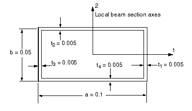
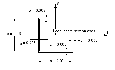
A box-section is shown in Figure 1. The dimensions shown in Figure 1 are for the main members of the two trusses in the crane. The dimensions of the beam sections for the bracing members are shown in Figure 2.


- In the Model Tree, double-click the Profiles container to create a box profile for the main members of the truss structures; then, create a second profile for the internal and cross bracing. Name the profiles
MainBoxProfileandBraceBoxProfile, respectively. Use the dimensions shown in Figure 1 and Figure 2 to complete the profile definitions. - Create one Beam section for the main members of the truss structures and one for the internal and cross bracing. Name the sections
MainMemberSectionandBracingSection, respectively.- For both section definitions, specify that section integration will be performed before the analysis. When this type of section integration is chosen, material properties are defined as part of the section definition rather than in a separate material definition.
- Choose
MainBoxProfilefor the main members' section definition, andBraceBoxProfilefor the bracing section definition. - Click the tab, and enter the Young's and shear moduli noted earlier in the appropriate fields of the data table.
- Enter the Section Poisson's ratio in the appropriate text field of the Edit Beam Section dialog box.
- Assign
MainMemberSectionto the geometry regions representing the main members of the trusses andBracingSectionto the regions representing the internal and cross bracing members. Use the Part list located in the context bar to retrieve each part. You can ignore theTruss-allpart since it is no longer needed.