Creating the sketch plane

You must create an appropriate datum plane on which to sketch the profile of the extruded cut.

Context:

The flange includes a small hole used for lubrication, as shown in Figure 1.
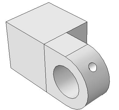
Figure 1. Isometric shaded view of the hinge with the lubrication hole.

Creating the hole in the desired location requires an appropriate datum plane on which to sketch the profile of the extruded cut, as shown in Figure 2.
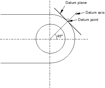
Figure 2. Two-dimensional view of the datum plane's position with respect to the hinge piece.

You sketch a circle on the datum plane, which is tangent to the flange, and Abaqus/CAE extrudes the circle normal to the datum plane and normal to the flange to create the lubrication hole.

There are three operations involved in creating the datum plane:

  • Creating a datum point on the circumference of the flange.

  • Creating a datum axis running between two datum points.

  • Creating a datum plane through the datum point on the circumference and normal to the datum axis.
  1. From the main menu bar, select ToolsDatum.

    Abaqus/CAE displays the Create Datum dialog box.

  2. Create a datum point along the curved edge of the flange through which the datum plane will pass. From the Create Datum dialog box, choose the Point datum type.
  3. From the list of methods, click Enter parameter.
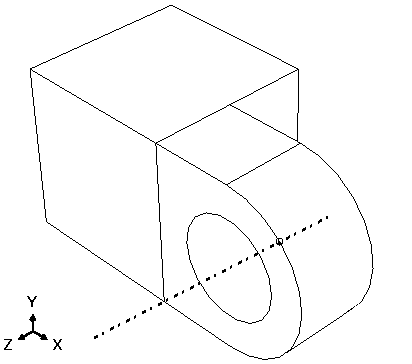
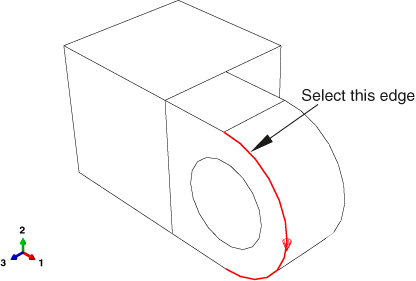
  4. Select the curved edge, as shown in Figure 3. Note the direction of the arrow indicating an increasing edge parameter from 0.0 to 1.0. You cannot change the direction of this arrow.

    Figure 3. Create a datum point along the curved edge of the flange.

  5. In the text box in the prompt area, enter a normalized edge parameter and press Enter. If the arrow direction is the same as in Figure 3, enter 0.25 as the normalized edge parameter; if the arrow points in the opposite direction, enter 0.75 as the normalized edge parameter.

    Abaqus/CAE creates a datum point along the selected edge.

  6. Create a datum axis that will define the normal to the datum plane. From the Create Datum dialog box, choose the Axis datum type. Click the 2 points method.

    Abaqus/CAE highlights the points that can be used to create the datum axis.

  7. Select the point at the center of the hole (created when you sketched the hole's profile) and the datum point on the curved edge.

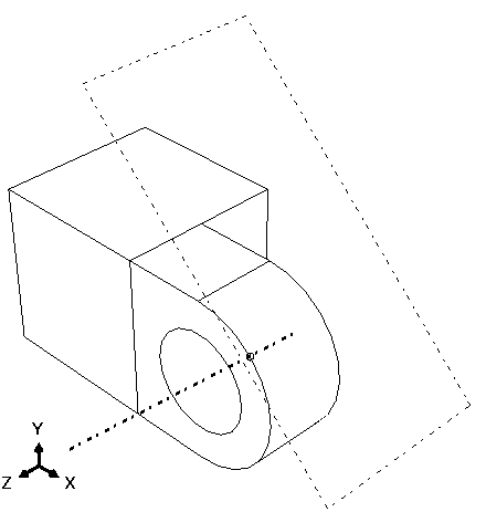
    Abaqus/CAE displays a datum axis passing through the two points, as shown in Figure 4.

    Figure 4. Create a datum axis defined by two datum points.

  8. The final step is to create the datum plane normal to the datum axis. From the Create Datum dialog box, choose the Plane datum type. Click the Point and normal method.
  9. Select the datum point on the curved edge as the point through which the datum plane will pass.
  10. Select the datum axis as the edge that will be normal to the datum plane.

    Abaqus/CAE creates the datum plane, as shown in Figure 5.

    Figure 5. Create a datum plane normal to the datum axis.