Incompatible mode elements | ||
| ||

These enhancements to the deformation gradient are entirely internal to an element and are not associated with nodes positioned along the element edges. Unlike incompatible mode formulations that enhance the displacement field directly, the formulation used in Abaqus does not result in overlapping material or a hole along the boundary between two elements, as shown in Figure 2.

Furthermore, the formulation used in Abaqus is extended easily to nonlinear, finite-strain simulations, something which is not as easy with the enhanced displacement field elements.
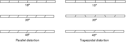
Incompatible mode elements can produce results in bending problems that are comparable to quadratic elements but at significantly lower computational cost. However, they are sensitive to element distortions. Figure 3 shows the cantilever beam modeled with deliberately distorted incompatible mode elements: in one case with “parallel” distortion and in the other with “trapezoidal” distortion.

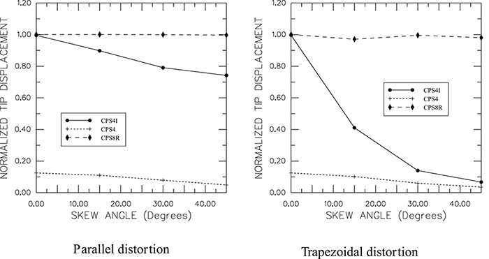
Figure 4 shows the tip displacements for the cantilever beam models. The tip displacements are normalized with respect to the analytical solution and plotted against the level of element distortion.

Three types of plane stress elements in Abaqus/Standard are compared: the fully integrated, linear element; the reduced-integration, quadratic element; and the linear, incompatible mode element. The fully integrated, linear elements produce poor results in all cases, as expected. On the other hand, the reduced-integration, quadratic elements give very good results that do not deteriorate until the elements are badly distorted.
When the incompatible mode elements are rectangular, even a mesh with just one element through the thickness of the cantilever gives results that are very close to the theoretical value. However, even quite small levels of trapezoidal distortion make the elements much too stiff. Parallel distortion also reduces the accuracy of the element but to a lesser extent.
Incompatible mode elements are useful because they can provide high accuracy at a low cost if they are used appropriately. However, care must be taken to ensure that the element distortions are small, which may be difficult when meshing complex geometries; therefore, you should again consider using the reduced-integration, quadratic elements in models with such geometries because they show much less sensitivity to mesh distortion. In a severely distorted mesh, however, simply changing the element type will generally not produce accurate results. The mesh distortion should be minimized as much as possible to improve the accuracy of the results.