Full integration | ||
| ||

Several different finite element meshes were used in Abaqus/Standard simulations of the cantilever beam problem, as shown in Figure 2. The simulations use either linear or quadratic, fully integrated elements and illustrate the effects of both the order of the element (first versus second) and the mesh density on the accuracy of the results.

The ratios of the tip displacements for the various simulations to the beam-theory value of 3.09 mm are shown in Table 1.
| Element | Mesh Size (Depth × Length) | |||
|---|---|---|---|---|
| 1 × 6 | 2 × 12 | 4 × 12 | 8 × 24 | |
| CPS4 | 0.074 | 0.242 | 0.242 | 0.561 |
| CPS8 | 0.994 | 1.000 | 1.000 | 1.000 |
| C3D8 | 0.077 | 0.248 | 0.243 | 0.563 |
| C3D20 | 0.994 | 1.000 | 1.000 | 1.000 |
The linear elements CPS4 and C3D8 underpredict the deflection so badly that the results are unusable. The results are least accurate with coarse meshes, but even a fine mesh (8 × 24) still predicts a tip displacement that is only 56% of the theoretical value. Notice that for the linear, fully integrated elements it makes no difference how many elements there are through the thickness of the beam. The underprediction of tip deflection is caused by shear locking, which is a problem with all fully integrated, first-order, solid elements.
As we have seen, shear locking causes the elements to be too stiff in bending. It is explained as follows. Consider a small piece of material in a structure subject to pure bending. The material will distort as shown in Figure 3.

Lines initially parallel to the horizontal axis take on constant curvature, and lines through the thickness remain straight. The angle between the horizontal and vertical lines remains at 90°.
The edges of a linear element are unable to curve; therefore, if the small piece of material is modeled using a single element, its deformed shape is like that shown in Figure 4.

For visualization, dotted lines that pass through the integration points are plotted. It is apparent that the upper line has increased in length, indicating that the direct stress in the 1-direction, , is tensile. Similarly, the length of the lower dotted line has decreased, indicating that is compressive. The length of the vertical dotted lines has not changed (assuming that displacements are small); therefore, at all integration points is zero. All this is consistent with the expected state of stress of a small piece of material subjected to pure bending. However, at each integration point the angle between the vertical and horizontal lines, which was initially 90°, has changed. This indicates that the shear stress, , at these points is nonzero. This is incorrect: the shear stress in a piece of material under pure bending is zero.
This spurious shear stress arises because the edges of the element are unable to curve. Its presence means that strain energy is creating shearing deformation rather than the intended bending deformation, so the overall deflections are less: the element is too stiff.
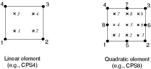
Shear locking only affects the performance of fully integrated, linear elements subjected to bending loads. These elements function perfectly well under direct or shear loads. Shear locking is not a problem for quadratic elements since their edges are able to curve (see Figure 5). The predicted tip displacements for the quadratic elements shown in Table 1 are close to the theoretical value. However, quadratic elements will also exhibit some locking if they are distorted or if the bending stress has a gradient, both of which can occur in practical problems.

Fully integrated, linear elements should be used only when you are fairly certain that the loads will produce minimal bending in your model. Use a different element type if you have doubts about the type of deformation the loading will create. Fully integrated, quadratic elements can also lock under complex states of stress; thus, you should check the results carefully if they are used exclusively in your model. However, they are very useful for modeling areas where there are local stress concentrations.
Volumetric locking is another form of overconstraint that occurs in fully integrated elements when the material behavior is (almost) incompressible. It causes overly stiff behavior for deformations that should cause no volume changes. It is discussed further in Materials.