Geometry and model
The problem geometry and loading are depicted in Figure 1: a 203-mm-long and 25.4-mm-wide specimen with a total skin thickness of 2.632 mm and maximum flange thickness of 1.88 mm, loaded in tension along the length direction. For the model in which the loading is simulated through prescribed displacements, the free gauge length is 127 mm. The skin thickness direction is comprised of 14 composite plies; while the flange is made up of 10 plies, each having a uniform thickness of 0.188 mm.
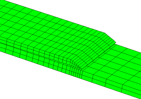
The finite element mesh for the three-dimensional model of the debonding problem is identical to that used in Davila (2003) except that the “decohesion” elements utilized in that reference to represent the skin/flange interface are replaced with Abaqus cohesive elements. Both the skin and the flange are modeled by two layers each of C3D8I elements. The interface between them is represented by COH3D8 elements, with the cohesive element mesh sharing nodes with the matching C3D8I meshes of the flange and the skin on either side. The model has a total of 828 solid elements and 174 cohesive elements. As stated in Davila, the two tapered ends of the flange are discretized differently to eliminate model symmetry and to prevent simultaneous delamination from occurring at both ends. The analysis includes a thermal loading step prior to the mechanical loading to simulate the residual stresses in the specimen due to a difference of 157°C between the curing temperature and room temperature. The temperature difference causes residual stresses at the skin/flange interface due to the fact that the thermal expansion coefficients of both the skin and flange material are orthotropic (even though they are specified to be the same) and the ply layups in the skin and flange are different.


