Geometry and model
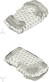
The mesh shown in Figure 1 is used in this example to model a fuel tank and its support straps. The mesh uses 2812 3-node shell elements (S3R), with the support straps modeled with 32 2-node beam elements (B31). Depending on the desired accuracy and detail of the solution, the analyst may identify some regions of the mesh in which additional refinement, or second-order elements, would be appropriate. The fuel tank would fit within a box of dimensions 450 mm × 200 mm × 680 mm. An internal pressure of 7 × 10⁻³ MPa is applied statically to the tank.
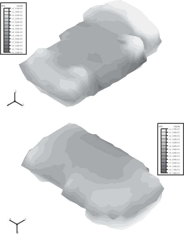
Analyses are conducted for a uniform shell thickness of 5 mm and for a spatially varying shell thickness in the range 1.38 mm to 9.35 mm (see Figure 2), which is a more accurate representation of the tank. The uniform thickness analysis provides a comparison to judge the effects of variable thickness. The overall volume of plastic modeled in the variable thickness analysis is about 93% of that in the uniform thickness analysis. For the variable thickness analysis the shell cross-section indicates that the shell thickness is to be interpolated from nodal values specified with nodal thickness. For elements with more than one integration point, this approach results in a thickness that can vary over the element.
The materials are modeled as isotropic elastic. The plastic fuel tank has a Young's modulus of 0.6 GPa and a Poisson's ratio of 0.3. The steel support straps have a Young's modulus of 206.8 GPa and a Poisson's ratio of 0.29. Geometrically nonlinear effects are significant in this example, so geometric nonlinearity is included in the step.


