Geometry and material
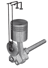
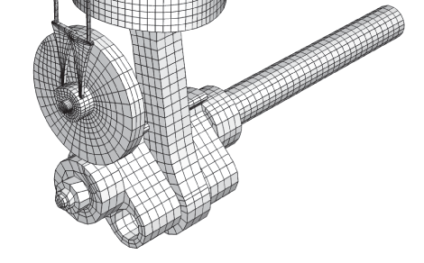
The multi-body system discussed here is the simplified one-piston engine model depicted in Figure 1 and in the detail shown in Figure 2. The model consists of several parts that are constrained together using connector elements. Each part is modeled either as a fully deformable regular mesh, a rigid body, or a substructure. The connections between parts are idealized using coupling constraints and connector elements. On each part a coupling constraint is used to constrain a few nodes near the connection points so that the connection forces get distributed to a finite area, much like in the physical model. The reference nodes in the coupling constraint are then used to define appropriate connector elements between neighboring parts that enforce the desired kinematic linkage between bodies.
The two parts of the crankshaft are rigidly connected using a BEAM connector element. The connecting rod between the crankshaft and the piston's head has HINGE connections at both ends. The gear transmission (2:1 gear ratio) between the crankshaft and the valve-cam is modeled using an equation constraint between two rotational degrees of freedom. An analytically defined rigid surface is used to model the contact surface of the cam. This surface is rigidly attached to the larger gear used to spin the cam. The contact between the cam followers and the cam is modeled using a single node on each cam follower's tip defined using a node-based surface. The connections between cam followers and push rods and between push rods and valve rockers are modeled using JOIN connectors. The valve rockers use HINGE connections about fixed points in space (the engine block is not modeled). The valve rockers are pushing against the spring loaded valves. The valve springs are precompressed and are defined using CARTESIAN connectors together with the reference lengths and angles for constitutive response and the connector elasticity behavior. The valve seats and the cylinders are not modeled. Steel material properties are used for all parts. The model is actuated by fixing the available components of relative motion to spin the right end of the crankshaft for a little more than two full revolutions. In some of the analyses the connector friction behavior is used to model frictional effects in the connector elements. Plasticity effects are specified in connectors in some of the analyses.
