Modeling
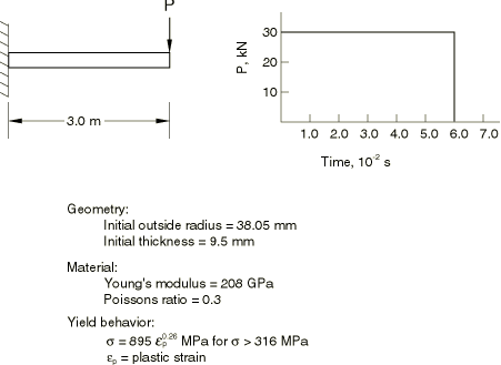
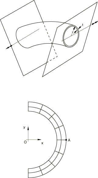
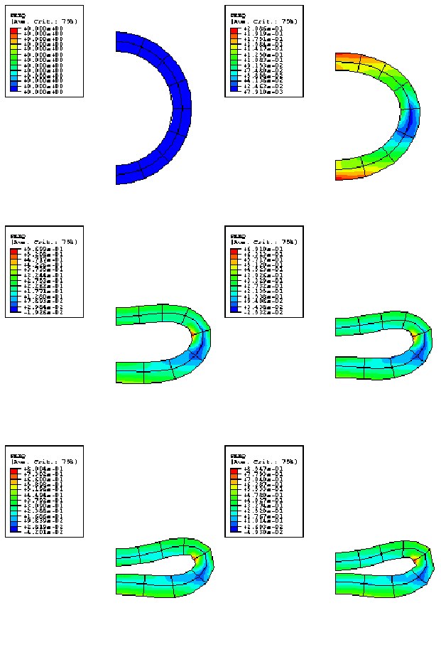
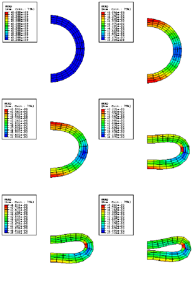
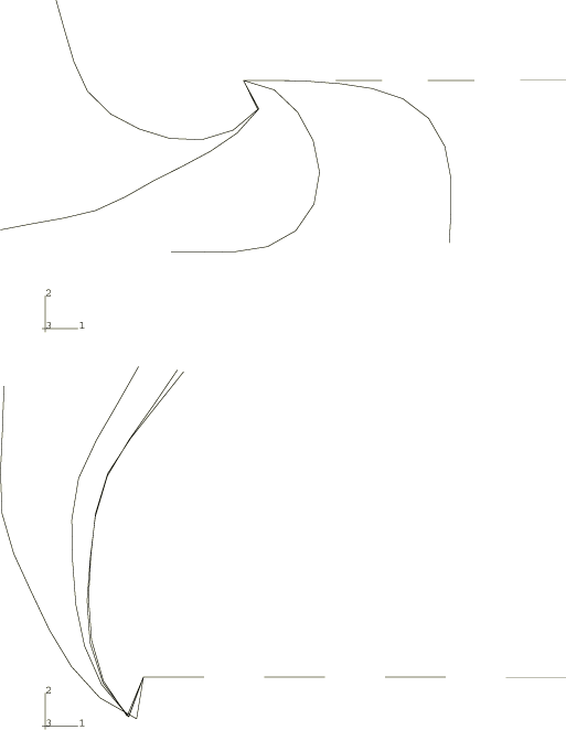
The problem is shown in Figure 1. To investigate the static collapse of the section, we consider a unit length of an initially straight pipe subjected to a pure bending moment and assume that plane sections remain plane. We can think of this unit length of pipe as being bounded at its ends by rigid walls and imagine the bending to be achieved by rotation of the walls relative to each other, the end sections being allowed to distort only in the plane of the walls (see Figure 2). With this idealization the pipe section can be modeled and discretized using generalized plane strain elements, as shown in Figure 2. Bending occurs about the x-axis, and symmetry conditions are prescribed along the y-axis. There will not be symmetry about the x-axis because of the Poisson's effect. To remove rigid body motion in the y-direction, point A is fixed in that direction. Symmetry implies no x-displacement at 0 and no rotation of the section about the y-axis. 4-node and 8-node generalized plane strain elements are used. In addition to the four or eight regular nodes used for interpolation, these elements require one extra reference node that is common to all elements in the model. Degree of freedom 3 at the reference node is the relative displacement between the boundary planes, while degrees of freedom 4 and 5 are the relative rotations of these planes.
Since the problem involves bending the pipe cross-section, regular fully integrated 4-node elements will not provide accurate results, especially when the pipe is fairly thin, because they will suffer from “shear locking”—they will not provide the bending deformation because to do so requires that they shear at their integration points and this shearing requires an unrealistically large amount of strain energy. This problem is avoided by integrating the elements only at their centroids but the elements then exhibit singular modes—modes of deformation that do not cause strain. Abaqus uses orthogonal hourglass generalized strains and associated stiffness to avoid such spurious singular mode behavior. Although these techniques are not always reliable, they can work well and do so in this example. The problem is also modeled with the fully integrated incompatible mode element CPEG4I and the modified triangular element CPEG6M. CPEG4I elements do not have any hourglass modes and perform well in bending. For additional discussion of these points see Performance of continuum and shell elements for linear analysis of bending problems.
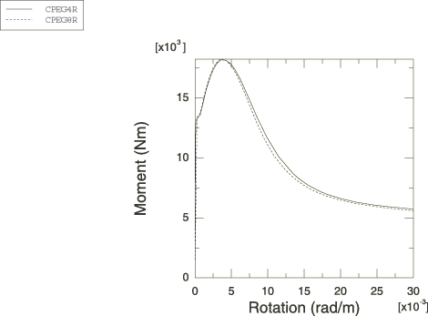
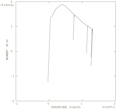
For the dynamic analysis of the pipe whip event the pipeline is modeled with 10 beam elements of type B21. These are planar beam elements that use linear interpolation of displacement and rotation. The moment-curvature relation obtained from the static analysis (shown in Figure 5) is used in the nonlinear general cross-section to define the bending behavior of the beams. A definition for the axial force versus strain behavior of the beams is also required and is provided by conversion of the uniaxial stress-strain relation given in Figure 1 into force versus strain by multiplying the stress by the current area, A, of the cross-section. This current area is computed from the original cross-sectional area by assuming that the material is incompressible, so , where l is the current length and is the original length.
This definition of the beam section behavior provides for no interaction between the bending and axial stretching, although in most real cases there will actually be some interaction. However, this approximation is probably reasonable in this particular problem since the response is predominantly bending and no appreciable error is introduced by the little stretching that does occur.
