Geometry and model
This model simulates crimp forming. Modern automobiles contain several thousand crimp joints. In a crimp joint a multi-strand wire bundle is mechanically joined to an end terminal to provide electrical continuity across the joint. The portion of the terminal that is folded over and into the wire bundle during crimping is called the grip. Proper design of a crimp joint depends on a number of competing factors including the diameter and number of the wire strands; the thickness, length, and material of the grip; and the geometry and surface finish of the crimp tooling. Out-of-plane extrusion of the wire bundle and grip during crimping is a significant factor in crimp formation.
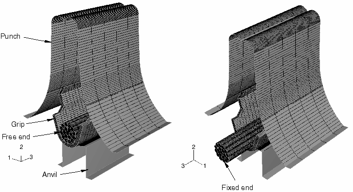
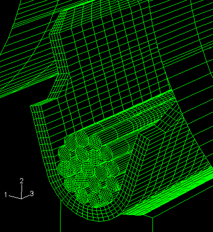
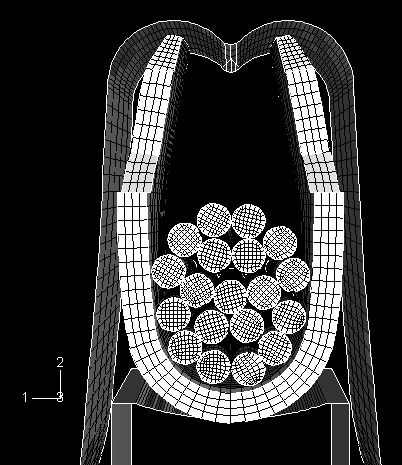
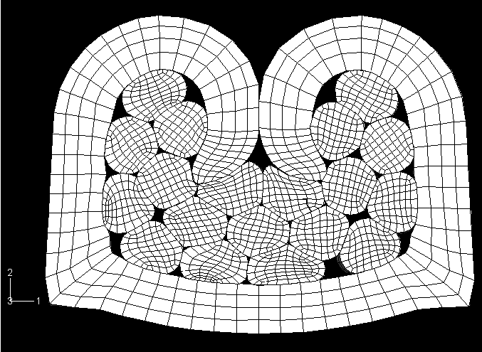
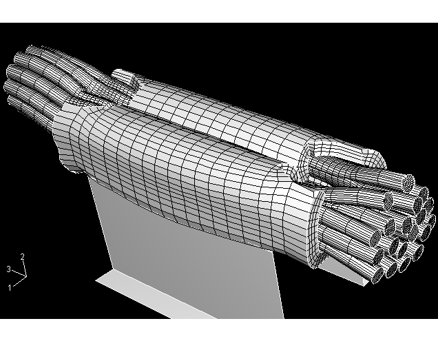
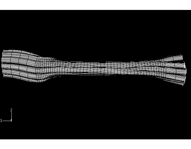
In this example the grip is 0.25 mm thick and has a 50% coin at the tips. Coining is done to help the grip arms curl over the wire bundle as they are pushed against the roof of the punch during crimping. The grip arm tips are 3.28 mm apart initially (wing tip width). A nineteen-strand wire bundle is used, with each strand having a 0.28 mm diameter. Figure 1 shows the model geometry prior to crimp forming. Figure 2 shows a close-up view of the wire-grip assembly.
The deformable wires and the grip are modeled with C3D8R elements. The punch and the anvil are modeled as rigid parts using R3D4 elements. The grip is made of a half hard copper alloy that is modeled as a von Mises elastic strain hardening plastic material with a Young's modulus of 112 GPa, a Poisson's ratio of 0.34, and a yield stress of 391 MPa. The wires are made of copper that is modeled as a strain hardening plastic material with a Young's modulus of 117 GPa, a Poisson's ratio of 0.35, and a yield stress of 241.5 MPa.
