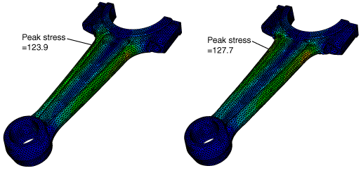
Application description
This example illustrates shape optimization of a connecting rod. Shape optimization makes slight modifications to the position of the surface nodes in the design area to achieve the optimized solution. Shape optimization is typically applied at the end of the design process when the general outline of a component is fixed and only minor changes are allowed. For more information, see Shape Optimization.
Geometry
The connecting rod model is a single orphan mesh part that was meshed with linear tetrahedral (C3D4) elements. The connecting rod is symmetric about the X–Z plane.
Materials
The connecting rod is made of an elastic material with a Young's modulus of 210 GPa, a Poisson’s ratio of 0.3, and a density of 7800 kg/m3.
Boundary conditions and loading
The displacement of the center node of the small end is constrained in the x- and y-directions, and the rotation of the center node is constrained in the y- and z-directions. For the center node of the big end, the displacement in the x- and z-directions and the rotation in the y- and z-directions are constrained.
During the first step a 25000 N load is applied to the center node of the small end of the connecting rod in the z-direction.
During the second step a −2000 N load is applied to the center node of the small end of the connecting rod in the z-direction and a 1750 N load is applied to the center node of the big end of the connecting rod in the y-direction. In addition, a rotation of 0.004 radians about the x-axis is applied to the center node of the big end.
Optimization features
The shape optimization is configured as described in the following sections.
Optimization task
This example creates a shape optimization task. To ensure good quality elements in the final design, mesh smoothing is applied to the elements in the design area.
Design area
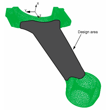
The design area of the model is the region that will be modified during the optimization, as shown in Figure 1. Regions are excluded from the design area because they are required for fixtures and for applying loads.
Design responses
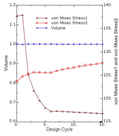
A design response is created for each step that determines the maximum von Mises stress in the design area. A third design response calculates the volume of the design area.
Objective function
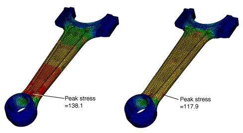
The objective function determines which of the two design responses results in the largest von Mises stress in the design nodes. The objective function then tries to minimize the maximum von Mises stress for that design response.
Constraint
The volume design response is configured as the single optimization constraint such that the total volume of the design area remains unchanged during the optimization process.
Geometry restrictions
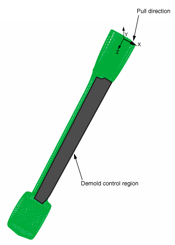
The example introduces a casting restriction by defining demold control geometry restrictions that are applied to the nodes in each half of the design area in the positive x- and negative x-directions. Figure 2 illustrates the demold control geometry restriction that is applied to one half of the design area in the positive x-direction.
