Adding a swept shell feature | ||||||
|
| |||||
Context:
You add a swept shell feature by first defining a sweep path, then defining a sweep profile. There are different methods available for defining each component:
You can define a sweep path either by sketching the path on a selected face or by selecting a series of edges or wires that you want the sweep path to follow. The sketch method provides greater flexibility but supports only two-dimensional paths. The edge/wire method enables you to define a three-dimensional sweep path along a feature such as a spline wire or a set of edges in a three-dimensional part.
You can define a sweep profile either by sketching a sweep profile using the Sketcher or by selecting one of the faces in your model as the profile. The sweep profile is initially perpendicular to the path; you can keep this orientation constant along the entire sweep path, or you can keep the sweep profile perpendicular to the sweep path as it is swept along its length.
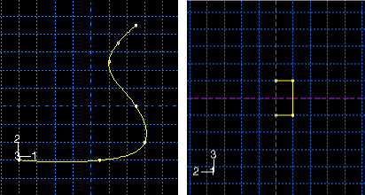
The sweep path (a spline) and the sweep profile are shown in the following figure:
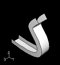
The resulting swept shell feature is shown in the following figure:
The sketch or set of edges defining the sweep path and the sketch, edge, or edges defining the sweep profile combine to define the swept shell feature; both the sweep path and the sweep profile can be modified using the Feature Manipulation toolset if you define them using the Sketcher. You can define a swept shell whose sweep profile is offset from the sweep path. In this case Abaqus/CAE moves the sweep path to a parallel location that passes through the sweep profile and creates the swept shell feature at that location.
As you define your sweep feature, you can apply a twist or draft to it. For more information about these tools, see What types of features can you create?. You can toggle on Keep profile normal constant to maintain the same orientation for the sweep profile as it travels along the sweep path; if this option is toggled off, the sweep profile orientation changes with the normal to the sweep path. In addition, you can toggle on Keep internal boundaries in the Feature Manipulation toolset to maintain any faces or edges that are generated between the swept shell feature and the existing part. The internal boundaries can create regions that can be structured or swept meshed without having to resort to partitioning.
 tool, located with the shell tools in the
  .
.  to return to the original view.