Creating a loft cut | |||||
|
| ||||
Context:
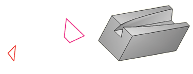
You add a loft cut by creating two or more sections from selected edges and by defining one or more loft paths. Loft sections and the resulting loft cut are illustrated in the following figure (the loft path is not shown in this figure):
You can allow Abaqus/CAE to define a single loft path using a smooth path to connect the center of each loft section (as in the previous figure). If you allow Abaqus/CAE to define the path, you can apply tangency methods to the start and end sections of the loft. The curve and tangencies define the path of the loft feature between sections. Alternatively, you can define one or more loft paths by selecting curves that connect a point on each loft section to a point on the next loft section. Each loft path must provide a continuous line connecting each consecutive loft section. If a loft path is not smooth (if there is more than one tangent to any point along the path), Abaqus/CAE will display an error message when you try to create the loft. For more information about loft sections, loft paths, and loft tangencies, see What is lofting?.
You do not use the Sketcher while adding a loft feature. As a result, all of the edges that define the loft sections and the loft paths must exist in the part geometry before you create the loft. To create a loft path or to create a nonplanar loft section, you can use the  tool, located with the wire tools in the Part module toolbox, to create a spline wire (see Adding a point-to-point wire feature, for more information).
 tool, located with the cut tools in the