Adding a point-to-point wire feature | |||||||
|
| ||||||
Context:
Assembly-level wire features are nonmeshable. The wire feature contains wires connecting points from the part or assembly in the current viewport or connecting points from the part or assembly to ground. To model connectors you must define one or more wire features on your assembly. When you create a wire feature on a part or an assembly, you can create a geometry set that includes the wires defined in the wire feature. In addition, when you create a wire feature on a part, you can create geometry sets that include the vertices defined in the wire feature.
To add a wire feature on a part, select from the main menu bar in the Part module. The point-to-point wire tool is always available in the Part module, regardless of the modeling space of the part in the current viewport. To add a wire feature on an assembly, select from the main menu bar in the Interaction module.
You add a point-to-point wire feature to a part by choosing a geometry type, polyline or spline; for assemblies you can add only a polyline wire feature. You can choose to imprint the wire on the existing part by creating edges, merge the wire with the existing part, or create the wire separate from the existing part. The wire merge options are available only in the Part module.
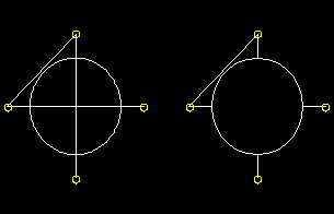
If you are creating polyline wires, you must next choose a point selection method and pick points to connect from the current part or assembly. You can choose to select disjointed points (i.e., not automatically connected end-to-end), chained points (i.e., automatically connected end-to-end), or points that are connected to ground. Abaqus/CAE connects the point pairs with a straight line or connects the points to ground depending on the method that you select. A polyline wire feature connecting four points in a part is illustrated in the following figure:
The planar shell feature is shown for reference. The image on the left shows the full length of the point-to-point wire using the Imprint wire or Separate wire options, while the image on the right shows a point-to-point wire connecting the same set of points using the Merge wire option.
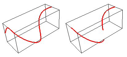
If you are creating spline wires on a part, the chained point selection method is the only one available. Abaqus/CAE calculates the shape of the curve by using a cubic spline fit between all points along the spline; in addition, the first and second derivatives of the spline are continuous. A spline wire feature is illustrated in the following figure: 
The rectangular solid feature is shown for reference. The image on the left shows the full length of the spline wire using the Imprint wire or Separate wire options, while the image on the right shows a spline wire connecting the same set of points using the Merge wire option.
During creation of the wire feature on a part or assembly, you can modify the point selections. For part-level wire features, in most cases, once you have created the wire feature, you cannot modify it directly. You may be able to remove a wire edge from the feature using the Geometry Edit toolset. (For more information, see Removing wire edges). If you want to change the points that are connected or the connection order, you must delete the wire and create a new wire connecting the desired points. Since the point-to-point wire is dependent on points created by other features, you can modify the wire by using the Feature Manipulation toolset to modify the features that created the points.
Although you cannot create a part with a nonplanar wire base feature, you can create a nonplanar point-to-point wire feature by using a single point in space as the base feature and entering coordinates for the remaining points. In this case the starting point is the only point that you can edit to modify the wire. You can also use datum points, in which case you can edit all points.
 tool, located with the wire tools in the
  tool, located in the
  to select the points that the wire will connect.
  , and reselect a point. The selection in the viewport is updated to show the newly edited point.
 .
. .
.