Controlling the display of thermal fluid pipe elements

Rendering of thermal fluid pipe elements is available in the Visualization module for undeformed, deformed, and contour plots only. There is no deformation associated with thermal fluid pipe elements; the deformed and undeformed plots are the same.

If you use thermal fluid pipe elements to model the flow of a liquid through a pipe in your analysis, you can use the View ODB Display Options to visualize the fluid pipe along with the fluid pressure, fluid temperature, and wall temperature contours. To clearly visualize the contours and plot shapes, you should create a display group that contains only the thermal fluid pipe elements.

See Also
Selecting plot display options

Context:

When you select the regions individually, Abaqus/CAE renders the fluid region as a solid cylinder and the inner wall and outer wall as thin hollow cylinders. If you choose to render both the inner wall and outer wall, a thick-walled cylinder is displayed. Temperature variation across the wall is visible on the end caps. When you render multiple regions, only the outermost region is visible on the surface of the cylinder; all the selected regions are rendered at the end caps. Figure 1 shows the nodal temperature (NT11) on the inner wall and outer wall of a fluid pipe.
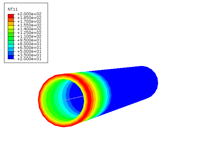
Figure 1. Rendering of fluid pipe thermal elements.

Abaqus/CAE renders thermal fluid pipe elements according to the current settings for color coding and translucency. When these settings change, the color and translucency of the thermal fluid pipe elements change as well. When thermal fluid pipe elements are displayed, Abaqus/CAE disables scaling and shrinking of the model.

  1. Locate the Fluid pipe thermal elements option.

    From the main menu bar, select View ODB Display Options . In the dialog box that appears, click the General tab.

  2. From the bottom of the dialog box, toggle on Fluid pipe thermal elements to render the thermal fluid pipe elements in your model.
  3. Toggle the following regions that you want to render:

    • Fluid region
    • Inner wall
    • Outer wall

  4. If desired, apply a Scale factor to the radius of each of the selected regions to increase or decrease its thickness. The default value is 1.
  5. Click OK to implement your changes and to close the dialog box.

    Abaqus/CAE displays the thermal fluid pipe elements in the selected part or assembly. By default, your changes are saved for the duration of the session. If you want to retain the changes you applied for subsequent sessions, save them to a file. For more information, see Saving customizations for use in subsequent sessions.