Grid format | ||
| ||

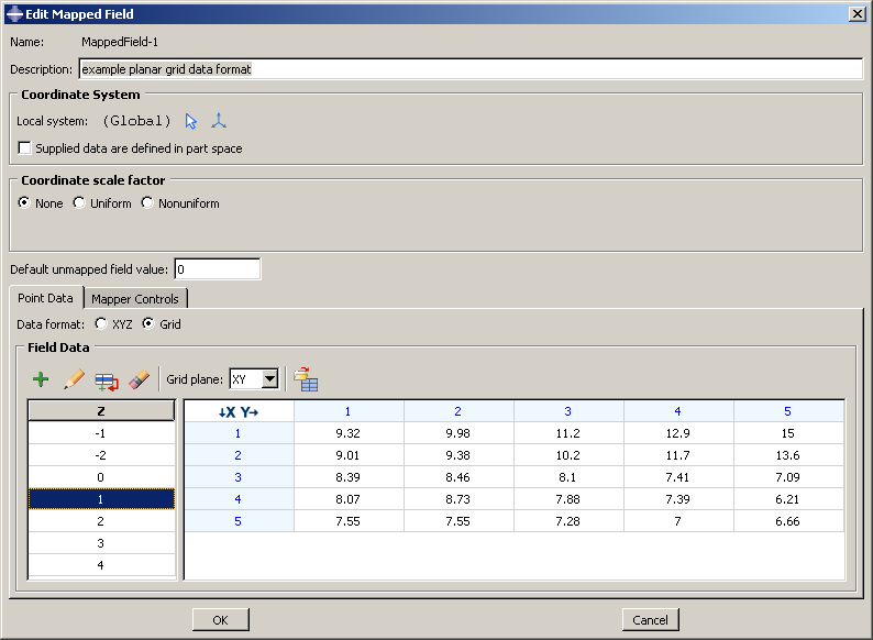
Grid data consist of a set of files, each containing a single plane. For example, you could have one file for the Z=3 plane. This file would contain a grid of X- and Y-coordinates and the field value at each point; for example:
a,  -2,    -1,    0,     1,     2
-2, 0.146, 0.141, 0.139, 0.137, 0.131
-1, 0.141, 0.121, 0.116, 0.111, 0.100
 0, 0.139, 0.116, 0.105, 0.101, 0.094
 1, 0.133, 0.129, 0.122, 0.114, 0.107
 2, 0.128, 0.120, 0.111, 0.102, 0.090
The X-coordinates appear in the first (left) column in this file, and the Y-coordinates are in the first (top) row, starting in the second position. The first position contains a dummy value that is ignored by Abaqus/CAE when you import the file into the data table in the Create Mapped Field dialog box. In the example file above, the dummy value is the character a; you can use any value in this position since it will be ignored.
The values in each row of a grid data file can be separated by any combination of spaces, tabs, or commas; each space, tab, or comma is considered a single field delimiter.
Your complete set of grid data files must include one file for each plane; for example, the X–Y planes at Z=0, Z=1, Z=2, Z=3. The Y–Z, X–Z, Y–X, Z–Y, and Z–X planes can also be used. You choose between the different grid planes in the Create Mapped Field dialog box.
If your grid data files have any missing field values, Abaqus/CAE interpolates to fill in the missing points; you do not need to fill in these missing values in the Create Mapped Field dialog box.
If you use a cylindrical or spherical local coordinate system, the appropriate coordinates must be given in the grid data files; see Coordinate system for point cloud mapped fields.