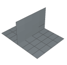
If a part
has branches, as shown in
Figure 1,
creating an offset solid mesh is not straightforward because the direction in
which to offset is ambiguous in the region of the branch.
Figure 1. The direction in which to offset is ambiguous in the region of the
branch.
To help you mesh this configuration,
Abaqus/CAE
provides the option to copy the elements in the region of the branch to a set.
You can then do the following:
Use display groups to remove the set containing elements in the region
of the branch from the orphan mesh.
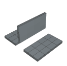
Create offset solid meshes from the non-branching regions that remain,
as shown in
Figure 2.
Figure 2. Create offset solid meshes from the non-branching regions.
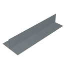
Use display groups to show only the set containing the branch, as shown
in
Figure 3.
Figure 3. Use display groups to show only the set containing the
branch.
Create an offset solid mesh from one side of the branching region. Take
care that the offset direction is correct (Abaqus/CAE
indicates the offset direction by coloring the element faces). In addition, do
not delete the base shell elements until you have finished offsetting the
branch.
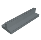
Create an offset solid mesh from the other side of the branching region,
as shown in
Figure 4.
Figure 4. The offset mesh in the branching region.
Use display groups to show both regions.
Use the merge nodes tool in the
Edit Mesh toolset
to merge the offset meshes created in Steps 2, 4, and 5.